Scaricare la presentazione
La presentazione è in caricamento. Aspetta per favore

0
Il Backbone IP di Telecom Italia e le Politiche di Peering

1
Indice A Need For Speed Il Backbone IP/MPLS di Telecom Italia
Le Politiche di Peering Appendici

2
1. A Need For Speed

3
Bandwidth development is going to reach a “Moore Law” slope
Network bandwidth Bandwidth development is going to reach a “Moore Law” slope

4
Consumer bandwidth 2 HDTV + 1 SDTV 28 Mbps 2 Gaming channels 512 kbps
Services 2 HDTV + 1 SDTV 28 Mbps 2 Gaming channels 512 kbps VOIP kbps High Speed Internet Mbps Downstream Total downstream ~ 40 Mbps Upstream Total upstream ÷ 10 Mbps

5
Connectivity everything, everywhere & every time
SOON ANYTHING CAN BE CONNECTED WILL BE CONNECTED!

6
The big picture: Toward a seamless connectivity (Consumer)
MOBILE DATA C O N V E R G E N C E MOBILE 4 P L A Y FIXED VOICE VOIP/TOIP IP DATA IP DATA IPTV TV OTT/WEB 2.0 1990 1995 2000 2005 NOW …

7
Italian market scenario
Voice/Broadband Voice/Broadband/IPTV Voice/Broadband/IPTV/mobile Double Play solution Triple Play solution Quadruple Play solution CONVERGENT OFFERS The Italian fixed-voice market has been influenced by: the development of mobile operators that attract voice traffic through the advantage of mobility, a wide range of Value Added Services and high performance terminals; the cannibalization effect caused by the increasing penetration of alternative communication solutions (messaging, ing, chat). The Broadband market continued to grow but at a slowing rate and subject to an increasing competition. In 2006, competition intensified also in the Top Client/Data market, with pressure on average prices. In this increasingly challenging market Wireline Business Unit revenues decreased only slightly, while maintaining a level of profitability at the top of peers' range.
. The Broadband market continued to grow but at a slowing rate and subject to an increasing competition. In 2006, competition intensified also in the Top Client/Data market, with pressure on average prices. In this increasingly challenging market Wireline Business Unit revenues decreased only slightly, while maintaining a level of profitability at the top of peers range.")
8
Business Market: from “size-based” to “needs-based”
New requests from “business world”… Exchange data securely with business partners and public administration Develop a modular service offer to follow company evolution (from startup to maturity) Obtain reliable and seamless (fixed + mobile) solutions and caring Simplify business complexity and achieve productivity gains …required new approach… …and offers Public sector Professionals Vertical Shops Independent shop Large companies M/S location firms size-based Needs based
 Obtain reliable and seamless (fixed + mobile) solutions and caring. Simplify business complexity and achieve productivity gains. …required new approach… …and offers. Public sector. Professionals. Vertical Shops. Independent shop. Large companies. M/S location firms. size-based. Needs based.")
9
…and so? Customers have even more need to be broadband connected every time & everywhere Telecommunication Operators & Technology Suppliers are expected to satisfy this primary need… TECHNOLOGY HUMAN RESOURCES TLC BIG INVESTMENTS NEW PROCESSES RESEARCH …but having an eye for Revenues in a “TRIPLE WIN” logic: Customers: Good Innovative Services at fair prices TLC Operators: Market Growth enabled by New Technologies available at fair prices 3. Technology Suppliers: Market Growth

10
Telecom Italia main business: some figures
FIXED MOBILE Manages and develops fixed-line and internet services Around 22 million fixed lines 3.7 million km domestic fibre optic access and trunk network km European fibre optic backbone 11 million broadband clients (3.4 million in Europe outside Italy) broadband brand Started 10 years ago as a “pure mobile” voice company Now has transformed into a personal and multimedia communications powerhouse 36.3 million mobile lines supplied in Italy and 31.3 million in Brazil 6.1 million UMTS technology lines The company has succeeded in retaining its 40.3% market share in Italy mobile brand
 broadband brand. Started 10 years ago as a pure mobile voice company. Now has transformed into a personal and multimedia communications powerhouse million mobile lines supplied in Italy and 31.3 million in Brazil. 6.1 million UMTS technology lines. The company has succeeded in retaining its 40.3% market share in Italy. mobile brand.")
11
Telecom Italia Group strategic guidelines
Internal Growth reinforcing positioning in South America and Europe Adjacent market development (media, content, IT services) to defend domestic market positioning High Mobile Brazil Int’l BB ICT services Medium Market attractiveness Domestic Mobile IPTV and Contents Domestic Fixed & Broadband Low Maintaining leadership on domestic core business defending customer base and supporting profitability Low Medium High Competitive Positioning Market value Growth
 to defend domestic market positioning. High. Mobile. Brazil. Int’l. BB. ICT. services. Medium. Market attractiveness. Domestic. Mobile. IPTV and Contents. Domestic. Fixed & Broadband. Low. Maintaining leadership on domestic core business defending customer base and supporting profitability. Low. Medium. High. Competitive Positioning. Market value. Growth.")
12
2. Il Backbone IP/MPLS di TI

13
The MPLS strategy is in Telecom Italia strongly coupled with the overall NGN notion, that was first adopted in the IP/MPLS Core (or Backbone) and is now moving to the Metro/Regional area. The OPB (Optical Packet Backbone) paradigm was then created and deployed starting from year 2001, followed by the OPM (Optical Packet Metro).
 paradigm was then created and deployed starting from year 2001, followed by the OPM (Optical Packet Metro).")
14
NGN The NGN seismic wave propagates from the centre to the periphery
MPLS: the NGN cross platform glue that allows to evolve in terms of services, QoS and scalability NGN The NGN seismic wave propagates from the centre to the periphery

15
The drivers strong increase of the IP and data traffic for residential and business services, service and application driven deployment of new multimedia services, with a scalable network in terms of capacity and performances infrastructure CAPEX optimisation, investing in the most advanced and future safe technologies with a lower cost per bit operational costs reduction in the network: technological platforms rationalization old technologies replacement NOC concentration

16
What does CAPEX optimisation mean in OPB in brief ?
IP traffic Capex The IP traffic carried by OPB doubles every 12 15 months, so the necessary link capacity (20G redundant link capacity by end 2001 and 800G by end 2007) The capex remains basically constant (or increase at most slightly) year by year, considering of course also the price drift and the technological evolution the capacity grow 40 times, in 7 years of almost constant capex
 The capex remains basically constant (or increase at most slightly) year by year, considering of course also the price drift and the technological evolution. the capacity grow 40 times, in 7 years of almost constant capex.")
17
the innovative and brave decision in 2001
a substantial innovation of the National Voice and IP Backbone - based on optical and IP/MPLS technologies - started in Y2001 a Multiservice MPLS Core not a catch phrase on the slides, but the deployment of a live network; not a green field project but the evolution of the previous IP backbone

18
An old 2001 slide: the NGN genesis started in the Core/Backbone
Revenue generation focus Cost efficiency focus SERVICE MANAGEMENT PLATFORM Voice Video Data Voice & Video telephony Services WIRELINE ACCESS OPTICAL PACKET BACKBONE Data Communication Services WIRELESS ACCESS Content Delivery Services Q slide

19
OPB, a single IP/MPLS Multiservice Core
a unique IP/MPLS BackBone “OPB” (Optical Packet BackBone) has been so developed from 2001 to aggregate and transport all kind of traffic (Fixed Voice, Data and Multimedia) from/to Retail and Wholesale Customer. the packet backbone has to assure a very high availability to the Voice traffic, comparable with the PSTN network (the so-called “Five Nines Availability”) then the resiliency of OPB is one of the mission critical aspects and it is achieved by the phisical (total redundant equipments, cards and links) and the logical routing level (MPLS-TE, Fast IGP convergence, Preventive Rerouting) moreover, another important goal was to hide telephone traffic from “public” IP Data traffic and to guarantee different level of QoS for each type of service MPLS and MPLS-TE technology was chosen to satisfy these needs
 has been so developed from 2001 to aggregate and transport all kind of traffic (Fixed Voice, Data and Multimedia) from/to Retail and Wholesale Customer. the packet backbone has to assure a very high availability to the Voice traffic, comparable with the PSTN network (the so-called Five Nines Availability ) then the resiliency of OPB is one of the mission critical aspects and it is achieved by the phisical (total redundant equipments, cards and links) and the logical routing level (MPLS-TE, Fast IGP convergence, Preventive Rerouting) moreover, another important goal was to hide telephone traffic from public IP Data traffic and to guarantee different level of QoS for each type of service. MPLS and MPLS-TE technology was chosen to satisfy these needs.")
20
The road from IBS to OPB and OPB2
2005 - 2008 The road from IBS to OPB and OPB2 VR VE BZ MO RI PI AN PG PE TA CZ CT Nola M I PD TS BS BO TO GE FI PA RM NA BA SV AL BG CO 2001 - 2004 1995 - - 2000 VR VE BZ MO RI PI AN PG PE CA TA CZ CT Nola M I PD TS BS BO TO GE FI PA RM NA BA SV AL BG CO BA CRS tecnology in the Inner Core, main Outer Core PoPs and also some secondary OC PoPs. All STM-64 Gb/s links; in some POPs also multiple 10G links MI BS TS TO PD BO GE FI RM BA NA PA 2 main PoPs 12 secondary PoPs E3 and E1 links 32 PoPs: 4 Inner Core, 28 Outer Core POPs diffserv QoS, MPLS TE and VPN; GSR technology STM-1 and STM-16 links; STM-64 in IC POPs

21
the current OPB architecture
Inner Core (4 POPs, 2 in RM & 2 in MI) BZ CO BG BS Main POP (8) TS Outer Core M I Secondary PoP (20) TO VE VR AL PD 2 x STM64 MO BO 2 x STM16 32 POPs 110 Core Routers and 96 L2/L3 aggregation Multilayer Switches for Edge Devices Optical Long Haul lambdas Inner Core with multiple 10Gbps links 27 POP in dual-homing with 10Gbps links (2xStm64xPOP or 4xStm64xPOP) 1 POP in dual-homing with 2.5Gbps links (4xStm16xPOP) total Core link capacity: almost 800 Gbps Peering capacity: about 200 Gbps total router switching capacity: 20 Terabit/s GE RI SV 12 x STM64 AN FI PG PI PE RM BA NL NA TA CA CZ PA CT [updated December 2007]
 BZ. CO. BG. BS. Main POP (8) TS. Outer Core. M I. Secondary PoP (20) TO. VE. VR. AL. PD. 2 x STM64. MO. BO. 2 x STM POPs. 110 Core Routers and 96 L2/L3 aggregation Multilayer Switches for Edge Devices. Optical Long Haul lambdas. Inner Core with multiple 10Gbps links. 27 POP in dual-homing with 10Gbps links (2xStm64xPOP or 4xStm64xPOP) 1 POP in dual-homing with 2.5Gbps links (4xStm16xPOP) total Core link capacity: almost 800 Gbps. Peering capacity: about 200 Gbps. total router switching capacity: 20 Terabit/s. GE. RI. SV. 12 x STM64. AN. FI. PG. PI. PE. RM. BA. NL. NA. TA. CA. CZ. PA. CT. [updated December 2007]")
22
The OPB general Services Scenario
IP/MPLS trasport for: Data Services: Internet Access Public IP national transport for fixed and mobile services VPN MPLS IP-TV Voice Services: Class4 and Class5 Business & Residential Mobile

23
Class 4 replacement: BBN, the OPB implementation
BBN Class4: more then MPLS-TE Tunnel has been already deployed on OPB (full mesh of 23 OPB POPs) with FRR, in order to achieve a complete disjoint control and forwarding plane Class 5 New Class5 services has open BBN resources to the Public IP plane, with similar QoS requirements A D M OLO/PLMN SGU Area Gateway S T 1 STM-1 Ethernet Switch Con funz . routing E1 GE POP BBN OPB iMSS 6509 Vism con indirizzi IP privati V con indirizzi IP pubblici
 with FRR, in order to achieve a complete disjoint control and forwarding plane. Class 5. New Class5 services has open BBN resources to the Public IP plane, with similar QoS requirements. A. D. M. OLO/PLMN. SGU. Area. Gateway. S. T. 1. STM-1. Ethernet. Switch. Con. funz. . routing. E1. GE. POP. BBN. OPB. iMSS Vism. con indirizzi IP privati. V. con indirizzi IP pubblici.")
24
some brand new services and functionalities on OPB
the IP/MPLS Technologies enabled Telecom Italia to move to OPB also the Mobile Voice Traffic the same requirements already met for C4 Replacement Project in 2001 have been satisfied also for new UMTS over IP traffic the same MPLS-TE architecture already used for the fixed Voice Traffic has been used for all TI’s “voice” POP no additional costs were needed in terms of BackBone transport The introduction of IPv6 will be reached exploiting an IP/MPLS BackBone and the 6PE models

25
Mobile Voice Traffic over MPLS
MPLS-TE New Mobile POP Front End GE P MPLS-TE MSC voice FE GE PE OPB GE GE MGW MPLS-VPN L2 Voice L2/L3 Signalling Signalling PE The mobile voice traffic uses the same tunnel architecture and addressing schemes engineered for the BBN project. The signalling traffic is instead inserted in MPLS-VPNs, that uses OPB as a P-MPLS Transport layer

26
and the future is not here yet…
The overall NGN architecture and vision will be enriched as a natural development of OPB, considering the success of the original project. The main drivers are the fixed-mobile convergence, the triple-play challenge, the broadband and ultra broadband push and of course the new NGN2 paradigm

27
3. Le Politiche di Peering

28
Assioma 0 La politica sempre perseguita da Telecom Italia è quella di favorire il peering in ambito nazionale con gli altri operatori di telecomunicazioni e ISP.

29
Presenza Telecom Italia è presente in tutti i NAP italiani
Telecom Italia ha stabilito relazioni di peering con tutti gli operatori di TLC e ISP riconosciuti, comunque tramite i punti di presenza pubblici ai NAP o tramite accordi di peering privato con i maggiori operatori Energie e investimenti costanti per garantire affidabilità e capacità sempre crescenti Gateway di classe GigaSwitch Router 12x16 o superiore Banda Totale disponibile verso NAP di 50 Gbit/s Banda Totale verso peering privati di 25 Gbit/s

30
I punti interscambio Internet per OPB
Cliente con AS Peering Privato Peering Pubblico OPB/IBS ISP NAP Internet Verso Upstream Provider (Seabone)
")
31
Politiche di routing di OPB (IV)
Internet SeaBone 4 Peering OPB/IBS 2-3 ASxxx 1 accesso a pagamento AS-Cliente N.B. 2 = peering Privato, 3 = peering Pubblico; non è prevista la contemporaneità di un accesso a pagamento ad IBS ed un Peering Privato

32
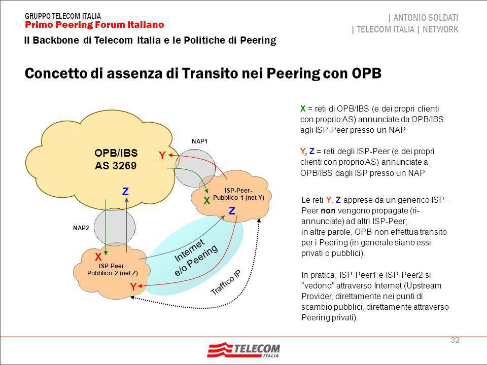
Concetto di assenza di Transito nei Peering con OPB
X = reti di OPB/IBS (e dei propri clienti con proprio AS) annunciate da OPB/IBS agli ISP-Peer presso un NAP Y, Z = reti degli ISP-Peer (e dei propri clienti con proprio AS) annunciate a OPB/IBS dagli ISP presso un NAP Internet e/o Peering OPB/IBS AS 3269 ISP-Peer- Pubblico 1 (net Y) Y Pubblico 2 (net Z) Z NAP1 NAP2 X Traffico IP Le reti Y, Z apprese da un generico ISP-Peer non vengono propagate (ri-annunciate) ad altri ISP-Peer; in altre parole, OPB non effettua transito per i Peering (in generale siano essi privati o pubblici). In pratica, ISP-Peer1 e ISP-Peer2 si "vedono" attraverso Internet (Upstream Provider, direttamente nei punti di scambio pubblici, direttamente attraverso Peering privati).
 annunciate da OPB/IBS agli ISP-Peer presso un NAP. Y, Z = reti degli ISP-Peer (e dei propri clienti con proprio AS) annunciate a OPB/IBS dagli ISP presso un NAP. Internet. e/o Peering. OPB/IBS. AS ISP-Peer- Pubblico 1 (net Y) Y. Pubblico 2 (net Z) Z. NAP1. NAP2. X. Traffico IP. Le reti Y, Z apprese da un generico ISP-Peer non vengono propagate (ri-annunciate) ad altri ISP-Peer; in altre parole, OPB non effettua transito per i Peering (in generale siano essi privati o pubblici). In pratica, ISP-Peer1 e ISP-Peer2 si vedono attraverso Internet (Upstream Provider, direttamente nei punti di scambio pubblici, direttamente attraverso Peering privati).")
33
Grazie per l’attenzione!
34
Appendice 1: NGN2

35
Telecom Italia NGN Project

36
Telecom Italia NGN2 deployment plan
NGN2 project plan develops in a period of 10 years and includes: Optic fiber for access network Digital Divide overtaking Complete substitution of traditional switching stations “circuit-switched” Stations number reduction (from to 8.200) Mobile network Network microcellular deployment macrocellular sites microcells for ultra BB on radio terminal FTTA and ROF technology for covering sites Fixed network Optic fiber for access network 1140 covered cities 2.200 stations 65% home passed Fiber links for remaining stations
 Mobile network. Network microcellular deployment macrocellular sites microcells for ultra BB on radio terminal. FTTA and ROF technology for covering sites. Fixed network. Optic fiber for access network covered cities stations. 65% home passed. Fiber links for remaining stations.")
37
FTTx NGN2 Project – A must!
At the moment no “killer application” for revenues boost related to FTTx development; but “bandwidth hungry” is always increasing Important benefits come from Opex and Capex saving against legacy programs for ADSL deployments Many historic network operators have announced FTTx projects with the perspective to provide triple/quadruple play services ( Mb/s) to a large part of their customers A trial phase is necessary to optimize the new technologies and to understand better the customers needs Key Project Figures (2016) ~ street cabinets out of ~ buildings covered ~ COs releases/compacted ~ Km of new fiber optics paths
 to a large part of their customers. A trial phase is necessary to optimize the new technologies and to understand better the customers needs. Key Project Figures (2016) ~ street cabinets out of ~ buildings covered. ~ COs releases/compacted. ~ Km of new fiber optics paths.")
38
Mobile Wireless Broadband
LTE, WIMAX ~100M HSPA ev. ~30/40M HSPA2+ ~14M The mobile network itself is the most important “customer” of NGN HSPA2 ~7M HSPA1 ~3M UMTS ~300K EDGE ~100K GSM ~10K Years 2007 2008 2009 2010

39
Telecom Italia Service Exposure: logic architecture
Service Exposure allows: Flexible intermediation of technological capabilities for the realization of innovative service models Technological de-pairing Network and IT capability separation from beneath technology Access reliability Dynamic resources allocation Service levels monitoring (SLAs, OLAs, …) Service Provider Content Provider Prosumer MVNO/ Second Brand Service Exposure Telecom Italia Network IT 39 39 39
 Service Provider. Content Provider. Prosumer. MVNO/ Second Brand. Service Exposure. Telecom Italia. Network. IT")
40
Appendice 2: Approfondimento sulle Politiche di Peering

41
Alcuni Concetti generali
Per politica di routing (in questo caso di peering) si intende un insieme di regole che disciplina lo scambio di informazioni di instradamento tra Autonomous System (AS). La manipolazione delle informazioni ricevute e/o trasmesse consente il controllo sui flussi di traffico scambiati con l'esterno Il protocollo utilizzato per realizzare le relazioni di peering è il BGP versione 4. BGP (Border Gateway Protocol) è appositamente progettato per lo scambio di informazioni di routing relative alla raggiungibilità delle destinazioni proprie di ciascun ISP (operatore Internet), ed implementa vari meccanismi atti ad evitare l'instaurarsi di loop, a consentire la segmentazione degli annunci su una molteplicità di sessioni ed ad assegnare a ciascun annuncio una priorità qualora esistano più percorsi verso la stessa destinazione Riguardo le relazioni di peering, si distinguono quelle realizzate in punti di interconnessione "Pubblici" (detti NAP, Neutral Access Point) o "Privati" (con interconnessione diretta tra i Backbone degli ISP tramite circuiti diretti trasmissivi). In entrambi i casi viene instaurata una sessione EBGP (External BGP) tra i router di ciascun Peer
 si intende un insieme di regole che disciplina lo scambio di informazioni di instradamento tra Autonomous System (AS). La manipolazione delle informazioni ricevute e/o trasmesse consente il controllo sui flussi di traffico scambiati con l esterno. Il protocollo utilizzato per realizzare le relazioni di peering è il BGP versione 4. BGP (Border Gateway Protocol) è appositamente progettato per lo scambio di informazioni di routing relative alla raggiungibilità delle destinazioni proprie di ciascun ISP (operatore Internet), ed implementa vari meccanismi atti ad evitare l instaurarsi di loop, a consentire la segmentazione degli annunci su una molteplicità di sessioni ed ad assegnare a ciascun annuncio una priorità qualora esistano più percorsi verso la stessa destinazione. Riguardo le relazioni di peering, si distinguono quelle realizzate in punti di interconnessione Pubblici (detti NAP, Neutral Access Point) o Privati (con interconnessione diretta tra i Backbone degli ISP tramite circuiti diretti trasmissivi). In entrambi i casi viene instaurata una sessione EBGP (External BGP) tra i router di ciascun Peer.")
42
Alcuni Concetti generali (segue)
OPB (Optical Packet Backbone) rappresenta il backbone IP/MPLS pubblico multiservizio di TI ed è l’evoluzione del BB di InterBusiness (AS3269); i clienti (Executive/Business o Residenziali) sono attestati a delle strutture/router di accesso (“Edge”) collegate ad OPB OPB è presente sui due NAP storici (il MIX ed il NAMEX) ed è anche presente al ToPIX ed al TIX OPB ha inoltre alcune relazioni di peering privato con ISP di grande caratura
 rappresenta il backbone IP/MPLS pubblico multiservizio di TI ed è l’evoluzione del BB di InterBusiness (AS3269); i clienti (Executive/Business o Residenziali) sono attestati a delle strutture/router di accesso ( Edge ) collegate ad OPB. OPB è presente sui due NAP storici (il MIX ed il NAMEX) ed è anche presente al ToPIX ed al TIX. OPB ha inoltre alcune relazioni di peering privato con ISP di grande caratura.")
43
I punti interscambio Internet per OPB
Cliente con AS Peering Privato Peering Pubblico OPB/IBS ISP NAP Internet Verso Upstream Provider (Seabone)
")
44
Alcune Definizioni (I)
Cosa è un ISP (Internet Service Provider ) per OPB: è un fornitore di accessi ad Internet (con listino ufficiale pubblicato di prodotti realizzati all’interno del proprio address space ed Autonomous System; quali, a titolo di esempio ed in via non esclusiva: linee di accesso dedicate, accessi dial up, accessi ADSL per clientela Business e Residenziale) è in possesso dell’autorizzazione Ministeriale per la fornitura di accessi ad Internet (rilasciata dal Ministero delle Comunicazioni ai sensi del D.L. n. 103 del 17/3/95 e del D.P.R. n. 420 del ) è registrato presso RIPE NCC o un registro equivalente come Local Internet Registry (avendo, quindi, facoltà di assegnare reti IP ai propri clienti) ha un proprio numero di Autonomous System pubblico rilasciato da un registro riconosciuto annuncia le proprie reti all’interno del proprio Autonomous System ha una propria connettività all'Internet globale indipendente dal Peering (sia esso Privato o Pubblico) con disponibilità della Full Internet Table mantiene aggiornato il Network Management Database pubblico di RIPE secondo le specifiche dettate dal documento RFC-2622 (detto anche RPSL)
 per OPB: è un fornitore di accessi ad Internet (con listino ufficiale pubblicato di prodotti realizzati all’interno del proprio address space ed Autonomous System; quali, a titolo di esempio ed in via non esclusiva: linee di accesso dedicate, accessi dial up, accessi ADSL per clientela Business e Residenziale) è in possesso dell’autorizzazione Ministeriale per la fornitura di accessi ad Internet (rilasciata dal Ministero delle Comunicazioni ai sensi del D.L. n. 103 del 17/3/95 e del D.P.R. n. 420 del ) è registrato presso RIPE NCC o un registro equivalente come Local Internet Registry (avendo, quindi, facoltà di assegnare reti IP ai propri clienti) ha un proprio numero di Autonomous System pubblico rilasciato da un registro riconosciuto. annuncia le proprie reti all’interno del proprio Autonomous System. ha una propria connettività all Internet globale indipendente dal Peering (sia esso Privato o Pubblico) con disponibilità della Full Internet Table. mantiene aggiornato il Network Management Database pubblico di RIPE secondo le specifiche dettate dal documento RFC-2622 (detto anche RPSL)")
45
Alcune Definizioni (II)
ISP-Peer ISP che effettua una sessione EBGP con la rete OPB, a titolo gratuito (a parte il costo trasmissivo, in caso di peering diretti), con lo scambio reciproco unicamente delle proprie rotte e delle rotte dei propri clienti (senza permettere quindi il transito verso Internet). E’ necessario sottolineare che un peering non è un servizio (con assistenza di postvendita e Help Desck) e non è soggetto a SLA; è unicamente un accordo tra operatori per ottimizzare le reciproche infrastutture di rete (perché impiegare la banda ITZ per traffico unicamente nazionale ?). Un peering è quindi un “fidanzamento” e può essere sciolto quando uno delle due parti non lo ritiene più opportuno (ogni ISP ha altre vie per raggiungere Intenet). Peering Privato peering con un ISP-Peer tramite un circuito dedicato (detto anche diretto); i Peering Privati rappresentano per OPB una eccezione Peering Pubblico peering con un ISP-Peer presso un punto di scambio pubblico (NAP: Neutral Access Point); questa modalità rappresenta la modalità di default AS-Cliente: Cliente di IBS che possiede un AS pubblico, con un proprio spazio di indirizzamento, ed utilizza un accesso pagante ad IBS (accesso collegato alle strutture di “Edge” di IBS), sul quale effettua una sessione EBGP
, con lo scambio reciproco unicamente delle proprie rotte e delle rotte dei propri clienti (senza permettere quindi il transito verso Internet). E’ necessario sottolineare che un peering non è un servizio (con assistenza di postvendita e Help Desck) e non è soggetto a SLA; è unicamente un accordo tra operatori per ottimizzare le reciproche infrastutture di rete (perché impiegare la banda ITZ per traffico unicamente nazionale ). Un peering è quindi un fidanzamento e può essere sciolto quando uno delle due parti non lo ritiene più opportuno (ogni ISP ha altre vie per raggiungere Intenet). Peering Privato peering con un ISP-Peer tramite un circuito dedicato (detto anche diretto); i Peering Privati rappresentano per OPB una eccezione. Peering Pubblico peering con un ISP-Peer presso un punto di scambio pubblico (NAP: Neutral Access Point); questa modalità rappresenta la modalità di default. AS-Cliente: Cliente di IBS che possiede un AS pubblico, con un proprio spazio di indirizzamento, ed utilizza un accesso pagante ad IBS (accesso collegato alle strutture di Edge di IBS), sul quale effettua una sessione EBGP.")
46
Politiche di routing di OPB (I)
i peering Pubblici vengono effettuati sull'AS 3269, possibilmente principalmente presso il MIX ed il Namex; oppure, quando richiesto o necessario, anche presso il TOPIX-NAP (componente Pubblica della piattaforma TOPIX) ed il TIX i peering Privati (o diretti) vengono effettuati sull'AS3269 fisicamente presso i POP OPB di Roma e Milano agli ISP-Peer vengono annunciate le reti aggregate di TI e le reti degli AS-Clienti; dagli ISP-Peer vengono accettate le reti aggregate proprie del peer (reti direttamente assegnate all'ISP dal RIPE) e le reti dei suoi AS-Clienti gli annunci appresi dagli ISP-Peer non vengono propagati verso SeaBone/Internet e verso gli altri ISP-Peer; in altri termini la rete OPB non effettua transito a favore degli ISP-Peer gli annunci appresi dai propri AS-Clienti vengono invece propagati verso SeaBone/Internet e verso gli ISP-Peer
 ed il TIX. i peering Privati (o diretti) vengono effettuati sull AS3269 fisicamente presso i POP OPB di Roma e Milano. agli ISP-Peer vengono annunciate le reti aggregate di TI e le reti degli AS-Clienti; dagli ISP-Peer vengono accettate le reti aggregate proprie del peer (reti direttamente assegnate all ISP dal RIPE) e le reti dei suoi AS-Clienti. gli annunci appresi dagli ISP-Peer non vengono propagati verso SeaBone/Internet e verso gli altri ISP-Peer; in altri termini la rete OPB non effettua transito a favore degli ISP-Peer. gli annunci appresi dai propri AS-Clienti vengono invece propagati verso SeaBone/Internet e verso gli ISP-Peer.")
47
Politiche di routing di OPB (II)
I[P] X: reti aggregate di IBS (X maiuscolo) Xc: reti dei Clienti IBS con proprio AS I: reti Internet da Seabone; I[ K]: contiene K P: reti dai Peering (sia Pubblici che Privati) TL-RR: Top Level RR: reti aggregate di IBS Internet Seabone P X, Xc I[X, Xc] X, Xc Peering (Pubblici e Privati) P I[P] X X, Xc Route Reflector OPB/IBS (AS3269) Cliente con proprio AS e reti (network) x Cliente con reti x e X di IBS Xc I[P] annuncio in EBGP delle reti K; K AS-Cliente (Xc) x
 Xc: reti dei Clienti IBS con proprio AS. I: reti Internet da Seabone; I[ K]: contiene K. P: reti dai Peering (sia Pubblici che Privati) TL-RR: Top Level RR: reti aggregate di IBS. Internet. Seabone. P. X, Xc. I[X, Xc] X, Xc. Peering. (Pubblici e. Privati) P. I[P] X. X, Xc. Route Reflector. OPB/IBS. (AS3269) Cliente con proprio AS e reti (network) x. Cliente con reti x e X di IBS. Xc. I[P] annuncio in EBGP delle reti K; K. AS-Cliente. (Xc) x.")
48
Politiche di routing di OPB (III)
Se un AS-cliente o ISP-Peer annuncia le proprie reti mediante più sessioni instaurate su collegamenti di diversa natura, vengono impostate le priorità in rete in modo da preferire gli annunci provenienti dai collegamenti secondo la seguente priorità (decrescente)
")
49
Politiche di routing di OPB (IV)
Internet SeaBone 4 Peering OPB/IBS 2-3 ASxxx 1 accesso a pagamento AS-Cliente N.B. 2 = peering Privato, 3 = peering Pubblico; non è prevista la contemporaneità di un accesso a pagamento ad IBS ed un Peering Privato

50
Attuali punti interscambio nazionali
Peering Privati (c/o POP RM e MI) MIX (Milano) OPB TIX (Firenze) NAMEX (Roma) TOPIX (componente NAP)
 MIX. (Milano) OPB. TIX. (Firenze) NAMEX. (Roma) TOPIX. (componente NAP)")
51
Paradigma generale per le politiche di Peering con gli ISP-Peer
Se un ISP-Peer di OPB è presente su più punti di peering (Peering Privati, MIX, NAMEX, TOPIX-NAP, TIX) dovranno essere impostate reciprocamente le priorità degli annunci in rete con le seguenti regole generali: dovrà essere preferito sempre il Peering Privato (se questo è presente) rispetto a quello Pubblico (presso un NAP); potrà esserci generalmente un solo peering Privato (o più privati) + uno Pubblico con un generico ISP-Peer come regola generale, un ISP-Peer avrà un peering Pubblico con OPB presso un unico NAP, possibilmente RM o MI; si valuterà (volta per volta) l’opportunità di gestire il peering su due punti di scambio (in funzione delle risorse disponibili presso i due NAP, sia di OPB che dell’ISP-Peer), a scopo di back-up qualora OPB ed un ISP-Peer decidano di effettuare due peering Pubblici presso due strutture di NAP (p.e. MIX e Namex), dovrà essere concordata (ed attuata in rete) la priorità di utilizzo dei peering in base a criteri di reciproca convenienza; la politica concordata non potrà essere arbitrariamente modificata da una delle due parti
 dovranno essere impostate reciprocamente le priorità degli annunci in rete con le seguenti regole generali: dovrà essere preferito sempre il Peering Privato (se questo è presente) rispetto a quello Pubblico (presso un NAP); potrà esserci generalmente un solo peering Privato (o più privati) + uno Pubblico con un generico ISP-Peer. come regola generale, un ISP-Peer avrà un peering Pubblico con OPB presso un unico NAP, possibilmente RM o MI; si valuterà (volta per volta) l’opportunità di gestire il peering su due punti di scambio (in funzione delle risorse disponibili presso i due NAP, sia di OPB che dell’ISP-Peer), a scopo di back-up. qualora OPB ed un ISP-Peer decidano di effettuare due peering Pubblici presso due strutture di NAP (p.e. MIX e Namex), dovrà essere concordata (ed attuata in rete) la priorità di utilizzo dei peering in base a criteri di reciproca convenienza; la politica concordata non potrà essere arbitrariamente modificata da una delle due parti.")
52
Concetto di assenza di Transito nei Peering con OPB
X = reti di OPB/IBS (e dei propri clienti con proprio AS) annunciate da OPB/IBS agli ISP-Peer presso un NAP Y, Z = reti degli ISP-Peer (e dei propri clienti con proprio AS) annunciate a OPB/IBS dagli ISP presso un NAP Internet e/o Peering OPB/IBS AS 3269 ISP-Peer- Pubblico 1 (net Y) Y Pubblico 2 (net Z) Z NAP1 NAP2 X Traffico IP Le reti Y, Z apprese da un generico ISP-Peer non vengono propagate (ri-annunciate) ad altri ISP-Peer; in altre parole, OPB non effettua transito per i Peering (in generale siano essi privati o pubblici). In pratica, ISP-Peer1 e ISP-Peer2 si "vedono" attraverso Internet (Upstream Provider, direttamente nei punti di scambio pubblici, direttamente attraverso Peering privati).
 annunciate da OPB/IBS agli ISP-Peer presso un NAP. Y, Z = reti degli ISP-Peer (e dei propri clienti con proprio AS) annunciate a OPB/IBS dagli ISP presso un NAP. Internet. e/o Peering. OPB/IBS. AS ISP-Peer- Pubblico 1 (net Y) Y. Pubblico 2 (net Z) Z. NAP1. NAP2. X. Traffico IP. Le reti Y, Z apprese da un generico ISP-Peer non vengono propagate (ri-annunciate) ad altri ISP-Peer; in altre parole, OPB non effettua transito per i Peering (in generale siano essi privati o pubblici). In pratica, ISP-Peer1 e ISP-Peer2 si vedono attraverso Internet (Upstream Provider, direttamente nei punti di scambio pubblici, direttamente attraverso Peering privati).")
53
Cosa è un NAP “classico” in sintesi
è un’infrastuttura di livello 2 (LAN con switch Ethernet), in genere centralizzata in un’unica sede oppure eventualmente distribuita a livello metropolitano gestita da un consorzio di operatori internet (ISP) costituito ad-hoc, senza scopi di lucro (e che si fa garante che il peering sia effettuato solo a titolo gratuito) con garanzie di continuità di servizio e di gestione di malfunzionamenti H24x365 che offre propri indirizzi pubblici sulla LAN di peering appartenenti ad un proprio AS pubblico e che tali indirizzi non verranno annunciati in Internet dove vengono effettuati Peering E-BGP, senza Transito verso Internet (per lo scambio delle rotte dei propri clienti direttamente connessi)... … senza dover creare una magliatura (n*(n-1)/2) di collegamenti diretti (CDN) tra i vari backbone degli n ISP (come nei Peering Privati) dove la magliatura è quindi solo logica tramite le sessioni E-BGP; le sessioni E-BGP, i filtri e le politiche di routing vengono concordate direttamente tra i vari ISP in genere, in un contesto nazionale, il numero di NAP ove gestire i peering sono (e devono essere) un numero limitato; stessa considerazione può essere applicata ai Peering Privati i quali devono essere instaurati solo con ISP di grande caratura
, in genere centralizzata in un’unica sede oppure eventualmente distribuita a livello metropolitano. gestita da un consorzio di operatori internet (ISP) costituito ad-hoc, senza scopi di lucro (e che si fa garante che il peering sia effettuato solo a titolo gratuito) con garanzie di continuità di servizio e di gestione di malfunzionamenti H24x365. che offre propri indirizzi pubblici sulla LAN di peering appartenenti ad un proprio AS pubblico e che tali indirizzi non verranno annunciati in Internet. dove vengono effettuati Peering E-BGP, senza Transito verso Internet (per lo scambio delle rotte dei propri clienti direttamente connessi)... … senza dover creare una magliatura (n*(n-1)/2) di collegamenti diretti (CDN) tra i vari backbone degli n ISP (come nei Peering Privati) dove la magliatura è quindi solo logica tramite le sessioni E-BGP; le sessioni E-BGP, i filtri e le politiche di routing vengono concordate direttamente tra i vari ISP. in genere, in un contesto nazionale, il numero di NAP ove gestire i peering sono (e devono essere) un numero limitato; stessa considerazione può essere applicata ai Peering Privati i quali devono essere instaurati solo con ISP di grande caratura.")
54
Tipica architettura di un NAP

Presentazioni simili

 064825120 - fax.>")


 Roma 24 marzo Organizzazione Key4biz FORUM 2011.>")


 abbiamo cominciato a lavorare utilizzando i maniera didattica tecnologie di tipo hardware.>")

