Scaricare la presentazione
La presentazione è in caricamento. Aspetta per favore

1
Stato del rivelatore mu Elettronica Sistema HV Prospettive per l’installazione Stato della costruzione delle camere Stato dei finanziamenti CORE Notizie dalla Collaborazione CSN1 – P.Campana – 7 luglio 2005

2
Le schede sono in test a Roma e domani saranno a LNF per essere montate sulle camere (M3R3-M5R3-M5R4) Elettronica (Lai-Sciubba) (Cagliari)
 Elettronica (Lai-Sciubba) (Cagliari)")
4
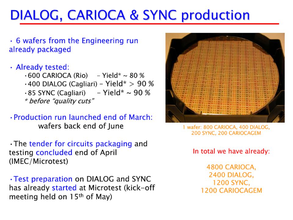
Test del CARIOCA: molto piu’ problematico del previsto In kind contribution dal Brasile (Rio): per vari problemi tecnici in forte ritardo L’IBM ha ritirato la licenza all’esportazione verso paesi non autorizzati (Brasile, Taiwan): di fatto l’opzione Brasile sfuma (aggravio costi, ca. 105 ksf) Il test dei chip e’ cruciale per poter avviare le procedure di vestizione e test delle camere con le Faraday cage e con le schede di FEE In ottobre dovrebbe partire la produzione di massa delle schede Cardiac (circa 10,000 in 5 mesi)
 Il test dei chip e’ cruciale per poter avviare le procedure di vestizione e test delle camere con le Faraday cage e con le schede di FEE In ottobre dovrebbe partire la produzione di massa delle schede Cardiac (circa 10,000 in 5 mesi).")
5
racks ottobre pareti ottobre/novembre crates + TB novembre cavi & fibre novembre LAYOUT DELL’ELETTRONICA

7
CRATES M12 x (4 x 2,5V + 2 x 3,3V + 3 x 5V channels = 4,5 modules + 1 crate) M22 x (3 x 2,5V + 3 x 3,3V + 2 x 5V channels = 4,0 modules + 1 crate) M32 x (3 x 2,5V + 3 x 3,3V + 2 x 5V channels = 4,0 modules + 1 crate) M42 x (2 x 2,5V + 2 x 3,3V + 2 x 5V channels = 3,0 modules + 1 crate) M52 x (2 x 2,5V + 2 x 3,3V + 2 x 5V channels = 3,0 modules + 1 crate) m.c.m. (4 x 2,5V + 3 x 3,3V + 3 x 5V channels = 5 modules) TOT 10 crates (5 modules each) LOW VOLTAGE MARATON 1 module 2 x (4,5V @ 50 A) M1 2 x (144+288+288+288 CARDIAC 72A+144A+144A+144A 1,0+1,5+1,5+1,5modules + 1 crate) M2 2 x ( 84+168+288+288 CARDIAC 42A+ 84A+144A+144A 0,5+1,0+1,5+1,5modules + 1 crate) M3 2 x ( 84+168+288+288 CARDIAC 42A+ 84A+144A+144A 0,5+1,0+1,5+1,5modules + 1 crate) M4 2 x ( 72+ 72+144+288 CARDIAC 36A+ 36A+ 72A+144A 0,5+0,5+1,0+1,5modules + 1 crate) M5 2 x ( 72+ 72+144+288 CARDIAC 36A+ 36A+ 72A+144A 0,5+0,5+1,0+1,5modules + 1 crate) m.c.m. 5,5 6 modules TOT 10 crates (6 modules each)
 TOT 10 crates (5 modules each) LOW VOLTAGE MARATON 1 module 2 x 50 A) M1 2 x ( CARDIAC 72A+144A+144A+144A 1,0+1,5+1,5+1,5modules + 1 crate) M2 2 x ( CARDIAC 42A+ 84A+144A+144A 0,5+1,0+1,5+1,5modules + 1 crate) M3 2 x ( CARDIAC 42A+ 84A+144A+144A 0,5+1,0+1,5+1,5modules + 1 crate) M4 2 x ( CARDIAC 36A+ 36A+ 72A+144A 0,5+0,5+1,0+1,5modules + 1 crate) M5 2 x ( CARDIAC 36A+ 36A+ 72A+144A 0,5+0,5+1,0+1,5modules + 1 crate) m.c.m. 5,5 6 modules TOT 10 crates (6 modules each).")
8
CABLES(1) LVDS cables (8 pairs)04.21.51.405.25616 x 10m = 56,2 km x 2,2 CHF = 82,4 k€ connectors 3M09.55.03.316.411232 x 1,05 CHF = 7,9 k€ assembling 5616 x 18 CHF = 67,4 k€ installation 2hx3pp/raw =48 manweek (2kCHF)64 k€157,7 k€ + 64 k€ ECS (I2C) cables (5 pairs)04.21.51. 1728 x10m = 17,3 km x 1,6 CHF = 18,5 k€ connectors 3M/RG4509.55.03.310.0/ 1728 x 0,8 + 1728 x 1 CHF = 2,1 k€ assembling 1728 x 14 CHF = 16,1 k€ interDIALOG cables (5 pairs) 5904 x 0,3 m =1,8 km x 1,6 = 1,9 k€ (+ 0,4 k€ IVA) interDIALOG 3M 5904 x 2 = 11808 x 0,8 CHF = 6,3 k€ (+ 1,3 k€ IVA) interDIALOG assembling 5904 x 0,5 € 3,0 k€ (+ 0,6 k€ IVA) ECS (CANbus)4x10 SB + 2x12 ODE + 10 DCS = 74 cables 74 x 80 m = 4,8 km x 2,2 CHF = 8,7 k€ connectors DP9 74+74 = 148 x 1,0 CHF = 0,1 k€ assembling 74 x 14 CHF = 0,7 k€ installation 2hx2pp/quad+ 1wx2pp/side = 10 manweek = 14 k€59,7 k€ + 14 k€ LV cables (2 conductors)04.08.61.445.11728 x 10 m = 17,3 km x 1,7 CHF = 19,6 k€ connectors (Molex) 1728 x 2 = 3456 x 1,4 CHF = 3,2 k€ assembling 1728 x 5,5 CHF = 6,3 k€ Grounding 04.01.31.(040.5/120.6) braids (120mm2+40mm2) 2,5km x 9,8 CHF + 0,4 km x 20CHF 21,6 k€ connectors 1380 x 1,7 CHF 1,6 k€ assembling 1380 x 2 CHF 1,8 k€ installation 1hx3pp/raw +4hx2pp/wall= 26 manweek = 35 k€54,1 k€ + 35 k€
 5904 x 0,3 m =1,8 km x 1,6 = 1,9 k€ (+ 0,4 k€ IVA) interDIALOG 3M 5904 x 2 = x 0,8 CHF = 6,3 k€ (+ 1,3 k€ IVA) interDIALOG assembling 5904 x 0,5 € 3,0 k€ (+ 0,6 k€ IVA) ECS (CANbus)4x10 SB + 2x12 ODE + 10 DCS = 74 cables 74 x 80 m = 4,8 km x 2,2 CHF = 8,7 k€ connectors DP = 148 x 1,0 CHF = 0,1 k€ assembling 74 x 14 CHF = 0,7 k€ installation 2hx2pp/quad+ 1wx2pp/side = 10 manweek = 14 k€59,7 k€ + 14 k€ LV cables (2 conductors) x 10 m = 17,3 km x 1,7 CHF = 19,6 k€ connectors (Molex) 1728 x 2 = 3456 x 1,4 CHF = 3,2 k€ assembling 1728 x 5,5 CHF = 6,3 k€ Grounding (040.5/120.6) braids (120mm2+40mm2) 2,5km x 9,8 CHF + 0,4 km x 20CHF 21,6 k€ connectors 1380 x 1,7 CHF 1,6 k€ assembling 1380 x 2 CHF 1,8 k€ installation 1hx3pp/raw +4hx2pp/wall= 26 manweek = 35 k€54,1 k€ + 35 k€.")
9
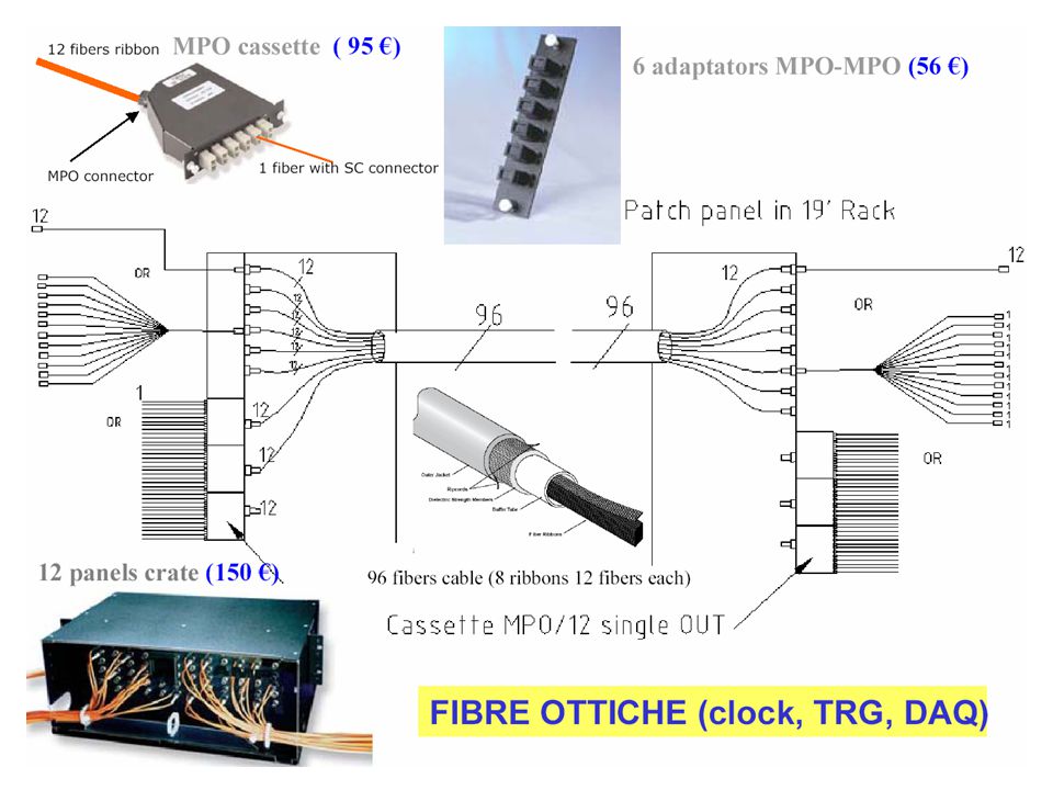
CABLES(2) IB-ODE 176 IB x 8 = 1408 x 10€14,1 k€ (+2,8 k€ IVA) 16,9 k€ HV cables (5 conductors)Kerpen1380x10m+384x0,5m=14,0kmx2,2CHF 20,5 k€ connectors custom vedi WPC assembling 1764 x 7,5 CHF = 8,8 k€ installation 2hx2pp/quad+1wx2pp/side = 10 manweek = 14 k€ 29,3 k€ + 14 k€ 317,7 k€ + 127 k€ = 444,7 k€ TRG (ODE-L0)M1 (48 ODE) FIBRE [48 x 0,5m ribbon + 4 custom + 48 x 10m ribbon] [8 x 6MPO-MPO + 1 x 4U] [6 40m 8ribbon] [48 x 1MPO-SC + 4 x 4U] M2-5 (2x 50 ODE) [2 x (50 x 0,5m ribbon + 4 custom + 50 x 30m ribbon] [2 x (9 x 6MPO-MPO + 1 x 4U)] [2 x 7 80m 8ribbon] [100 x 1MPO-SC + 9 x 4U] DATA (ODE-TELL1) M1 (48 ODE = 4 ribbon) [48 x 0,5m single + 0 custom + 4 x 10m ribbon] [1 x 6MPO-MPO + 0 x 4U] [1 40m 8ribbon] [4 x 1MPO-SC + 1 x 4U] M2-5 (2x 16+16+9+9 = 2 x 6 ribbon) [2 x (50 x 0,5m single + 0 custom + 6 x 30m ribbon] [2 x (1 x 6MPO-MPO + 0 x 4U)] [2 x 0 80m 8ribbon] [12 x 1MPO-SC + 1 x 4U] clock (TTCoc-ODE/PDM) M1+2xM2-5 (148 ODE + 10 PDM) [158 x 0,5m single + 0 custom + (48 x 10m single + 2 x 50 x 30m single)]
![CABLES(2) IB-ODE 176 IB x 8 = 1408 x 10€14,1 k€ (+2,8 k€ IVA) 16,9 k€ HV cables (5 conductors)Kerpen1380x10m+384x0,5m=14,0kmx2,2CHF 20,5 k€ connectors custom vedi WPC assembling 1764 x 7,5 CHF = 8,8 k€ installation 2hx2pp/quad+1wx2pp/side = 10 manweek = 14 k€ 29,3 k€ + 14 k€ 317,7 k€ k€ = 444,7 k€ TRG (ODE-L0)M1 (48 ODE) FIBRE [48 x 0,5m ribbon + 4 custom + 48 x 10m ribbon] [8 x 6MPO-MPO + 1 x 4U] [6 40m 8ribbon] [48 x 1MPO-SC + 4 x 4U] M2-5 (2x 50 ODE) [2 x (50 x 0,5m ribbon + 4 custom + 50 x 30m ribbon] [2 x (9 x 6MPO-MPO + 1 x 4U)] [2 x 7 80m 8ribbon] [100 x 1MPO-SC + 9 x 4U] DATA (ODE-TELL1) M1 (48 ODE = 4 ribbon) [48 x 0,5m single + 0 custom + 4 x 10m ribbon] [1 x 6MPO-MPO + 0 x 4U] [1 40m 8ribbon] [4 x 1MPO-SC + 1 x 4U] M2-5 (2x = 2 x 6 ribbon) [2 x (50 x 0,5m single + 0 custom + 6 x 30m ribbon] [2 x (1 x 6MPO-MPO + 0 x 4U)] [2 x 0 80m 8ribbon] [12 x 1MPO-SC + 1 x 4U] clock (TTCoc-ODE/PDM) M1+2xM2-5 (148 ODE + 10 PDM) [158 x 0,5m single + 0 custom + (48 x 10m single + 2 x 50 x 30m single)]](http://images.slideplayer.it/11/3295867/slides/slide_9.jpg "CABLES(2) IB-ODE 176 IB x 8 = 1408 x 10€14,1 k€ (+2,8 k€ IVA) 16,9 k€ HV cables (5 conductors)Kerpen1380x10m+384x0,5m=14,0kmx2,2CHF 20,5 k€ connectors custom vedi WPC assembling 1764 x 7,5 CHF = 8,8 k€ installation 2hx2pp/quad+1wx2pp/side = 10 manweek = 14 k€ 29,3 k€ + 14 k€ 317,7 k€ k€ = 444,7 k€ TRG (ODE-L0)M1 (48 ODE) FIBRE [48 x 0,5m ribbon + 4 custom + 48 x 10m ribbon] [8 x 6MPO-MPO + 1 x 4U] [6 40m 8ribbon] [48 x 1MPO-SC + 4 x 4U] M2-5 (2x 50 ODE) [2 x (50 x 0,5m ribbon + 4 custom + 50 x 30m ribbon] [2 x (9 x 6MPO-MPO + 1 x 4U)] [2 x 7 80m 8ribbon] [100 x 1MPO-SC + 9 x 4U] DATA (ODE-TELL1) M1 (48 ODE = 4 ribbon) [48 x 0,5m single + 0 custom + 4 x 10m ribbon] [1 x 6MPO-MPO + 0 x 4U] [1 40m 8ribbon] [4 x 1MPO-SC + 1 x 4U] M2-5 (2x = 2 x 6 ribbon) [2 x (50 x 0,5m single + 0 custom + 6 x 30m ribbon] [2 x (1 x 6MPO-MPO + 0 x 4U)] [2 x 0 80m 8ribbon] [12 x 1MPO-SC + 1 x 4U] clock (TTCoc-ODE/PDM) M1+2xM2-5 (148 ODE + 10 PDM) [158 x 0,5m single + 0 custom + (48 x 10m single + 2 x 50 x 30m single)]")
11
Elettronica (Frascati) Transition Boards324+56=380 (15% spare) per IB consegna prime TB testate - giugno per ODE consegna prototipi - fine luglio fine consegna TB testate – settembre IB176+34=210 172+38 (22%) produzione: ready to start (PRR) fine test delle IB – ottobre ODE148+32=180 152+28 (18%) produzione - da luglio a novembre test - da novembre a gennaio 2006 LV1728+272=2000 (16%) componenti preproduzione – giugno fine produzione – luglio
 Transition Boards324+56=380 (15% spare) per IB consegna prime TB testate - giugno per ODE consegna prototipi - fine luglio fine consegna TB testate – settembre IB176+34=210 (22%) produzione: ready to start (PRR) fine test delle IB – ottobre ODE148+32=180 (18%) produzione - da luglio a novembre test - da novembre a gennaio 2006 LV =2000 (16%) componenti preproduzione – giugno fine produzione – luglio")
12
Elettronica (Roma1) Service Boards156 + 19 test della preproduzione quasi completato partenza della produzione rimandata a dopo PRR PDM12 + 3 prototipo OK partenza al PRR TELL110 + 2 o 12 + 0 ? DAQ a 1 MHZ nuova architettura software (maggior bandwidth) produzione avviata per quasi tutto partenza del rimanente a settembre SPB7300 +1500 in fase di completamento la produzione degli spares alcune modifiche in atto per M1R2 (INFN->CERN)
 produzione avviata per quasi tutto partenza del rimanente a settembre SPB in fase di completamento la produzione degli spares alcune modifiche in atto per M1R2 (INFN->CERN).")
13
a)Max voltage: + 3 kV b)Voltage resolution: 10 V or better c)Current per channel230 μA at most (on M1R2) d)Current resolution: 50 nA or better (to spot bad chambers) e)Switch off of the single HV channel (or reduce considerably the HV) f)Radiation hardness (for systems inside the exp. area) 2.3 kRad M1 M2 M3 M4 M5 R1 GEMs 0.107 0.028 0.021 0.016 R2 0.228 0.078 0.015 0.010 0.009 R3 0.169 0.041 0.006 0.005 0.006 R4 0.068 0.010 0.004 0.002 0.003 Currents in mA per gap Based on 5 10 32 luminosity and safety factors (x2 in M1, x5 in M2-M5) IL SISTEMA DI ALTA TENSIONE - SPECIFICHE
 2.3 kRad M1 M2 M3 M4 M5 R1 GEMs R R R Currents in mA per gap Based on luminosity and safety factors (x2 in M1, x5 in M2-M5) IL SISTEMA DI ALTA TENSIONE - SPECIFICHE.")
14
GroupingM1M2M3M4M5 R111111 R211111 R311111 R412222 Best option 3408 HV ch/4944 GroupingM1M2M3M4M5 R111111 R211111 R311111 R414444 Minimal option 2640 HV ch/4944 HV connectors to allow daisy-chain Jumpers

15
The available options The architecture was discussed in the LHCb HV workshop we had in March. At the moment the rad-tol option is cheaper even for commercial systems Moreover non-rad-tol option has some intrinsic cost overheads O(100 kCHF): cables+PP Candidates (rad-tol) CAEN Easy with 32 channels modules UF CMS Muon End Caps HV with 36 channels modules Univ. Florida CMS Module CAEN EASY 3000-A3535 module
: cables+PP Candidates (rad-tol) CAEN Easy with 32 channels modules UF CMS Muon End Caps HV with 36 channels modules Univ. Florida CMS Module CAEN EASY 3000-A3535 module.")
16
Abbiamo sviluppato un connettore HV custom (“reverso”) che ci permette di ottimizzare gli spazi, i costi e gli impieghi d’uso (M/F – pannello/cavo) Ai due sistemi viene richiesto 2 anni di garanzia supporto tecnico off-site negli anni a venire UF prevede gli spares dall’inizio UF parteciperebbe come “ditta”. La soluzione migliore è probabilmente fare una gara per un sistema da 2640 canali con opzione per l’acquisto del mancante fino a 3400 Ad oggi, a nostra conoscenza, la differenza di prezzo e’ notevole.

17
Procedura e tempi L’attuale Money Matrix prevede un costo di 410 kCHF suddiviso fra CERN (235 kCHF) e INFN (175 kCHF) Per vari motivi (economici) vorremmo attestare la spesa a ca. 350 ksf Di questi 50 k€ = 75 kCHF sono SJ a Roma2 richiesta sblocco La gara sarà fatta dal CERN Le specifiche tecniche sono pronte E’ necessaria una lettera da parte nostra con l’autorizzazione a includere UF nella gara l’impegno alla suddivisione dei costi CERN/INFN I tempi sono stretti: per un ordine a Settembre si può avere il sistema dopo 1 anno con il 25% a Luglio 2006 Saranno richiesti 2 moduli di preproduzione prima della produzione finale (montaggio dei connettori custom, regolaggi vari)
.")
18
Esperienza di CMS-UF Fabrizio Gasparini (PD), Proj. Leader dei Mu di CMS In CMS le camere ci sono solo nei Mu e in particolare Barrelcamere a drift alimentazione CAEN custom (-2,+2,+4 kV) End Capscamere MWPC PNPI con alimentazione UF/PNPI (+ 3kV) Il sistema CAEN è nato da un progetto al 5% fatto insieme a Padova (dal ’91). 2-3 anni fa la CAEN ci aveva proposto per LHCb una variante monotensione di tale sistema che voleva proporre per l’alimentazione delle EC di CMS. La gara poi non è stata fatta perché UF e PNPI hanno adottato il proprio sistema. La CAEN non ha proseguito lo sviluppo e per questo motivo non ce l’ha più offerto. Dice che CMS ha una buona esperienza dell’HV di UF con 200 camere EC già montate sull’esperimento e alimentate e non ci sono problemi. Dice che UF è un istituto molto attivo in CMS a tutti i livelli (e quindi non vi è particolare timore che possa scomparire da un momento all’altro)
 End Capscamere MWPC PNPI con alimentazione UF/PNPI (+ 3kV) Il sistema CAEN è nato da un progetto al 5% fatto insieme a Padova (dal ’91). 2-3 anni fa la CAEN ci aveva proposto per LHCb una variante monotensione di tale sistema che voleva proporre per l’alimentazione delle EC di CMS. La gara poi non è stata fatta perché UF e PNPI hanno adottato il proprio sistema. La CAEN non ha proseguito lo sviluppo e per questo motivo non ce l’ha più offerto. Dice che CMS ha una buona esperienza dell’HV di UF con 200 camere EC già montate sull’esperimento e alimentate e non ci sono problemi. Dice che UF è un istituto molto attivo in CMS a tutti i livelli (e quindi non vi è particolare timore che possa scomparire da un momento all’altro).")
19
Conclusioni (HV) Vorremmo dalla Commissione una indicazione chiara adesso Ritardare a settembre comporterebbe un ritardo di circa 3 mesi Un ritardo di 3 mesi farebbe sì che non avremmo modo di collegare all’HV la prima metà di camere già installate! Il punto cruciale è il confronto fra costi (e quindi segmentazione) e assistenza/affidabilita’. Va tenuto in considerazione la positiva esperienza di CMS sia per quanto riguarda il sistema che della solidità del gruppo di UF. A settembre non avremmo ulteriori elementi in mano mentre una decisione positiva adesso permetterebbe di far partire la gara (che comunque necessiterebbe di una approvazione semi-formale dall’INFN)
 e assistenza/affidabilita’. Va tenuto in considerazione la positiva esperienza di CMS sia per quanto riguarda il sistema che della solidità del gruppo di UF. A settembre non avremmo ulteriori elementi in mano mentre una decisione positiva adesso permetterebbe di far partire la gara (che comunque necessiterebbe di una approvazione semi-formale dall’INFN).")
20
M2R4/1 M4R4/1 M4R3/1 M5R4/1 M3R4/1 M3R4/2 M2R4/2 M4R3/2 M4R4/2 M2-M5 1 st part M2-M5 2 nd part M1 Last M1 produced PIANO di PRODUZIONE e di INSTALLAZIONE delle CAMERE

21
Installation plans (1) –FEE & FC mounting The schedule foresees that from 1/2/06 to 25/4/06 we must install: - INFN : 24x4 M2M3M4M5 R3 12x2 M4M5R2 + 100 M5 R4 ~ 230 chambers - PNPI : 96x3 M2M3M4 R4 ~ 300 chambers - CERN : 6x4 M2M3M4M5 R1 + 12x2 M2M3R2 ~ 50 chambers Taking into account the available time: PNPI : mount FC+FEE in 5 ch/day INFN : mount FC+FEE in 3 ch/per day CERN has to mount FEE (as FC is built in with chamber) It is feasible if: - the full startup is really in October; - 2 lines of dressing are available in Frascati and 3 in PNPI+CERN; - FC dressing and FEE tests do not show problems Some 50 FC ready by the end of July We plan to have in september/october a reasonable amount of FC to start the dressing at full speed
 –FEE & FC mounting The schedule foresees that from 1/2/06 to 25/4/06 we must install: - INFN : 24x4 M2M3M4M5 R3 12x2 M4M5R M5 R4 ~ 230 chambers - PNPI : 96x3 M2M3M4 R4 ~ 300 chambers - CERN : 6x4 M2M3M4M5 R1 + 12x2 M2M3R2 ~ 50 chambers Taking into account the available time: PNPI : mount FC+FEE in 5 ch/day INFN : mount FC+FEE in 3 ch/per day CERN has to mount FEE (as FC is built in with chamber) It is feasible if: - the full startup is really in October; - 2 lines of dressing are available in Frascati and 3 in PNPI+CERN; - FC dressing and FEE tests do not show problems Some 50 FC ready by the end of July We plan to have in september/october a reasonable amount of FC to start the dressing at full speed")
22
Installation plans (2) - Muon Chamber Installation at the pit Sept/05 – preparation of the areas and of the tooling for muon wall mounting Preparation of the chamber test area Oct-Nov/05 – Mounting of muon walls at the pit, together with shelves and cable- holders (8 walls > 9-10 weeks) Dec/05-Feb/06 – Cabling and piping Feb-Apr/06 – Mounting ½ M2 M3 M4 M5 : ~ 580 chambers in 12 weeks (2 teams, 5 ch/day) Sept-Nov/06 – as previous Jan-Mar/07 – Mounting M1: walls+cables+pipes+chambers These dates have uncertainties also due to: 1) cryogenics (end by July 05?) 2) beam pipe (June 06?) 3) LHC sector test (December 06?) The Teams Muon walls: Frascati Workshop (3pp) Chamber (final) tests: 1 team PNPI + 1 team INFN (1 tech+ 1 physicist) Chamber installation: 1 team PNPI + 1 team INFN + CERN (2 tech.+1 phys.) 5 ch./day/team Electronics installation: to be defined (starting when?)
 - Muon Chamber Installation at the pit Sept/05 – preparation of the areas and of the tooling for muon wall mounting Preparation of the chamber test area Oct-Nov/05 – Mounting of muon walls at the pit, together with shelves and cable- holders (8 walls > 9-10 weeks) Dec/05-Feb/06 – Cabling and piping Feb-Apr/06 – Mounting ½ M2 M3 M4 M5 : ~ 580 chambers in 12 weeks (2 teams, 5 ch/day) Sept-Nov/06 – as previous Jan-Mar/07 – Mounting M1: walls+cables+pipes+chambers These dates have uncertainties also due to: 1) cryogenics (end by July 05 ) 2) beam pipe (June 06 ) 3) LHC sector test (December 06 ) The Teams Muon walls: Frascati Workshop (3pp) Chamber (final) tests: 1 team PNPI + 1 team INFN (1 tech+ 1 physicist) Chamber installation: 1 team PNPI + 1 team INFN + CERN (2 tech.+1 phys.) 5 ch./day/team Electronics installation: to be defined (starting when )")
23
Order placed (within budget) Some design modification Delivery of 1 st part end of August Work on traction system and nacelles not finished Work on M1 and on cooling just started General Infrastructure (CERN)
 Some design modification Delivery of 1 st part end of August Work on traction system and nacelles not finished Work on M1 and on cooling just started General Infrastructure (CERN)")
24
Schedule and Resources: For time being we have to focus on the cryo-side. Tasks for shielding wall side about 2 month later than indicated for cryo-side below. Refurbishing of zone behind M5. Work will be done in collaboration with the experimental area team in July 2005 Now until 19 August General support structure will be mounted by the LHCb experimental area team in Aug/Sep 2005 (3 weeks) Chamber support structure and chamber supports will be installed by technicians from LNF from October to November 2005 (4 weeks) The on detector gas piping will be done using industrial support November- December 2005 The on detector cabling will be done through the cabling service at CERN between December 2005 and January 2006 (8 weeks) -> We aim at having the preparations (at least on the cryo-side) completed by end of January 2006...
 Chamber support structure and chamber supports will be installed by technicians from LNF from October to November 2005 (4 weeks) The on detector gas piping will be done using industrial support November- December 2005 The on detector cabling will be done through the cabling service at CERN between December 2005 and January 2006 (8 weeks) -> We aim at having the preparations (at least on the cryo-side) completed by end of January")
25
LHCb si e’ dato una struttura organizzativa per l’analisi: i Physics Working Groups Convener: Schneider Production and decay modes (Vagnoni, Robbe) Flavor tagging (Calvi, Leroy) Decay time and mixing (Raven, Hunen) CP (Schmelling, Wilkinson) Rare decays (Andersen, Golutvin) Jets (Bay, Teubert) Anche nell’ambito di LHCb-Italia ci si sta organizzando per razionalizzare le risorse sul software e sull’analisi (specie per chi inizia adesso): circa una ventina di giovani Il gruppo di Syracuse e’ divenuto membro della Collaborazione Attivita’ su SW, Velo, Rich – circa 8 FTE – contributo previsto 1.5-2 MSF a spares, computing, upgrades (per ora certo solo 0.4 MSF, in settembre richiesta a NSF) Entro 2 anni revisione dello status di membro se finanziamento non adeguato Proposta di transizione del readout da 2 vie (L1 1MHz, HLT 40kHz) ad un singolo stream ad 1 MHz distribuito alla event builder farm (che non cambierebbe il no. di CPU) Forte semplificazione del sistema, accesso piu’ semplice ai dati, unificazione degli algoritmi >>> decisione finale in settembre
 Forte semplificazione del sistema, accesso piu’ semplice ai dati, unificazione degli algoritmi >>> decisione finale in settembre.")
26
Stato dei finanziamenti del rivelatore a mu Costruzioni camere: con i 66 kE richiesti completiamo l’impegno da MM (2170+50 ksf) >>> anche se con la finalizzazione degli ordini (Faraday C.+catodi+connettore HV) ci attendiamo di dover attingere alla contingenza che e’ nell’elettronica <<< Elettronica : rimangono circa 450 ksf nel 2006 (cavi, Tell1, installazioni) Sistemi : rimangono circa circa 400 ksf nel 2006 (Gas, HV, meccanica M1) Common fund : comprendiamo le impellenze della CSN1 (prevedere 840 ksf nel 2006) La situazione non e’ rosea e siamo al limite di tutte le cifre (vd es. test CARIOCA). Se non ci sono ulteriori sorprese, con un’oculata gestione del CORE e dei consumi possiamo pensare di avere un rivelatore funzionante nel 2007, senza dover (ri)tornare sul CORE. Tutti i gruppi sono coscienti della situazione finanziaria e fanno del loro meglio.
. Se non ci sono ulteriori sorprese, con un’oculata gestione del CORE e dei consumi possiamo pensare di avere un rivelatore funzionante nel 2007, senza dover (ri)tornare sul CORE. Tutti i gruppi sono coscienti della situazione finanziaria e fanno del loro meglio..")
Presentazioni simili


 Scopi del test (discussi tra di noi,con i referee ed al GruppoI a giugno)>")


Avvisi: Giovedi 28 marzo la lezione e sospesa. Nuovo indirizzo di Spedire messaggi e esercizi solo.>")

