Scaricare la presentazione
La presentazione è in caricamento. Aspetta per favore

1
s d E. Iacopini, CSN1 Napoli 20 Sett. 2005

2
Stato della Collaborazione Stato della Collaborazione (A. Ceccucci) Disegno dellapparato sperimentale Disegno dellapparato sperimentale (N. Doble, L. Gatignon) Stato della simulazione Stato della simulazione (G. Ruggiero) Dove siamo con i detectors Dove siamo con i detectors
 Disegno dellapparato sperimentale Disegno dellapparato sperimentale (N. Doble, L. Gatignon) Stato della simulazione Stato della simulazione (G. Ruggiero) Dove siamo con i detectors Dove siamo con i detectors.")
3
Proposal submitted to SPSC on June 11, 2005: We propose to measure the very rare decay K + + at the CERN SPS to make a decisive test of the Standard Model by extracting a 10% measurement of the CKM parameter |V td |. The open presentation to the SPSC is scheduled on September 27, 2005

4
Recent developments in the rare kaon decay community A few months ago the Fermilab Directorate endorsed the PAC recommendation not to pursue K + + at the Main Injector The physics of K + + was considered very important but a potential conflict for protons between the kaon and the neutrino possible programmes at Fermilab lead to this recommendation Very Recently the RSVP program was terminated: –The to e conversion experiment (MECO) and the K 0 experiment, ready to start construction at BNL, will not be built This leaves CERN and Japan (JPARC) as the only places where an ultra-rare kaon decay experiments are currently envisaged However, to be completely fair, one should also mention: –Plans at Protvino as mentioned at KAON2005 –Plans at Frascati to study K S at an upgraded phi factory
 and the K 0 experiment, ready to start construction at BNL, will not be built This leaves CERN and Japan (JPARC) as the only places where an ultra-rare kaon decay experiments are currently envisaged However, to be completely fair, one should also mention: –Plans at Protvino as mentioned at KAON2005 –Plans at Frascati to study K S at an upgraded phi factory")
5
Strengthening P326 The demise of the US kaon program has triggered negotiations with members of KOPIO/CKM to join P326 The following groups have signed up since the proposal submission: –S Louis Potosi (Mexico, J. Engelfried) –Bolotovs group (Moscow, INR) Interest to join has been expressed by the following groups: –Fermilab (P. Cooper) –BNL (L. Littenberg) –British Columbia (D. Bryman) However, a possible participation of US groups is subject to: –DOE support towards a strong contribution to the construction of the detector (notably the RICH counter) –The involvement of US Universities in addition to National Labs (at least for BNL)
 –Bolotovs group (Moscow, INR) Interest to join has been expressed by the following groups: –Fermilab (P. Cooper) –BNL (L. Littenberg) –British Columbia (D. Bryman) However, a possible participation of US groups is subject to: –DOE support towards a strong contribution to the construction of the detector (notably the RICH counter) –The involvement of US Universities in addition to National Labs (at least for BNL).")
6
Endorsement of P326 R&D by SPSC From the draft minutes of the July 05 meeting: "The SPSC considers it important that an R&D programme continues concerned with the possibility of an experiment to measure the rare decay K + + "

7
CERN Program and Plans introduction to Round Table discussion on The Future of High Energy Physics ECFA-EPS Joint Session at HEPP-EPS 2005 International Europhysics Conference on High Energy Physics Lisbon, July 21 -27, 2005 Jos Engelen CERN

8
From Medium Term Plan, CERN/2615 Will determine the future course of high energy physics Detector completion/upgrade/in particular for luminosity upgrade ( 10 35 ) (~2014); requires R&D, machine and detectors Very limited neutrino programme (in scope) New initiatives include K + + ; why not K 0 0..? New initiatives may include a long term neutrino programme CERN working groups Proton Accelerators for the Future (PAF) and Physics Opportunities at Future Proton Accelerators (POFPA) New initiatives to appear in Budget Plan from 2006 (or maybe 2007) onwards Accelerator R&D includes EU funded networks, joint projects, design studies Linear colliders: Eurotev (generic) and CLIC (CERN and partners, collaboration, feasibility proof by 2009) EURISOL Design Study (including beta beams) No fully-fledged Neutrino Factory Design Study yet (2008 if EU support)
 and Physics Opportunities at Future Proton Accelerators (POFPA) New initiatives to appear in Budget Plan from 2006 (or maybe 2007) onwards Accelerator R&D includes EU funded networks, joint projects, design studies Linear colliders: Eurotev (generic) and CLIC (CERN and partners, collaboration, feasibility proof by 2009) EURISOL Design Study (including beta beams) No fully-fledged Neutrino Factory Design Study yet (2008 if EU support).")
9
Slides from Niels Doble & Lau Gatignon

10
Choice of K + momentum : (for 400 GeV/c proton momentum)
")
11
(2 RMS)
")
13
800 MHz ( /K/p) Solo i rivelatori upstream sono esposti a 800 MHz di fascio (8.6% K) … 10 MHz Kaon decays K+K+ + 1.5
 Solo i rivelatori upstream sono esposti a 800 MHz di fascio (8.6% K) … 10 MHz Kaon decays K+K")
18
Thanks to Giuseppe Ruggiero

19
Background kinematically constrained DecayBR K 2 0.634 + 0 0.211 + + - ( 0 0 )0.070 92% of total background + 0 forces us to split the signal region
 % of total background + 0 forces us to split the signal region")
20
Background not kinematically constrained Decay BR K e3 0.049 K 3 0.033 K 2 K 2 5.5×10 -3 + 0 + 0 1.5×10 -3 K e4 4×10 -5 K 4 1×10 -5 8% of total background Spoils the signal region

21
Background rejection Goal of P326: S/B 10 ~10 12 rejection 2-steps background rejection: 1) Kinematical rejection Region I: 0 < m 2 miss < 0.01 GeV 2 /c 4 Against K 2, + 0 Region II: 0.026 < m 2 miss < 0.068 GeV 2 /c 4 Against + 0, + +, + 0 0 2) Veto and Particle ID,, charged particles – e separation
 Kinematical rejection Region I: 0 < m 2 miss < 0.01 GeV 2 /c 4 Against K 2, + 0 Region II: < m 2 miss < GeV 2 /c 4 Against + 0, + +, ) Veto and Particle ID,, charged particles – e separation")
22
Sources of background Kinematical rejection inefficiency Resolution effects Non gaussian tails Beam pile – up Veto and particle ID inefficiency RICH – veto Simulation (Jurgen) Simulation (Oleg) Parameterization (Simulation in progress by Rome) (Data in progress: LKr by NA48/2, ANTI by Frascati) Simulated using Flyo Simulated using GEANT4 Simulated using Flyo
 Simulation (Oleg) Parameterization (Simulation in progress by Rome) (Data in progress: LKr by NA48/2, ANTI by Frascati) Simulated using Flyo Simulated using GEANT4 Simulated using Flyo")
23
Resolutions (Flyo MC) Gigatracker 300 x 300 m pixels 0.4% X0 per Spibes Simple reconstruction 2% inefficiency per station Double Spectrometer 80 m resolution in X and Y hits (125 m per view) 0.5% X0 per chamber Track momentum from fit Angle from first 2 chambers Fully efficient + 0 m 2 miss resolution PKPK K P track K Results: (P K )/P K = 4.2 x 10 -3 ( K ) = 16.7 rad (P )/P = 0.23% + 0.005% P (GeV/c) ( K ) = 60 – 20 rad (P = 10 – 50 GeV/c)
 Gigatracker 300 x 300 m pixels 0.4% X0 per Spibes Simple reconstruction 2% inefficiency per station Double Spectrometer 80 m resolution in X and Y hits (125 m per view) 0.5% X0 per chamber Track momentum from fit Angle from first 2 chambers Fully efficient + 0 m 2 miss resolution PKPK K P track K Results: (P K )/P K = 4.2 x ( K ) = 16.7 rad (P )/P = 0.23% % P (GeV/c) ( K ) = 60 – 20 rad (P = 10 – 50 GeV/c)")
24
Not gaussian tails (GEANT4) Simulation: Toy simulation of the Double Spectrometer, based on GEANT4 Interactions: Electromagnetic, Hadronic Reconstruction: Average material 0.5% X0 (no straws geometry) -ray production allowed No digitization, coordinates smeared with gaussians Effects: Tails in the reconstructed momentum and angle: smearing of the m 2 miss Spoiling of the rejection power for the kinematical constrained background + 0 30-35 GeV/c Approximation: Non gaussian effects in the Gigatracker not taken into account
 Simulation: Toy simulation of the Double Spectrometer, based on GEANT4 Interactions: Electromagnetic, Hadronic Reconstruction: Average material 0.5% X0 (no straws geometry) -ray production allowed No digitization, coordinates smeared with gaussians Effects: Tails in the reconstructed momentum and angle: smearing of the m 2 miss Spoiling of the rejection power for the kinematical constrained background GeV/c Approximation: Non gaussian effects in the Gigatracker not taken into account")
25
Beam pile-up (Flyo) Simulation: Accidental track superimposed in Gigatracker to the kaon track Accidental track generated according to the beam momentum bite, dimension and divergence Rate: 800 MHz SPIBES: time resolution 200 ps, inefficiency 2% HODOSCOPE: time resolution 80 ps Effect: The downstream track can be matched with the wrong track: danger expecially for Analysis: Only upstream tracks within 500 ps from the downstream track are considered good upstream tracks: 32% of events have >1 good track in Giga Track choice based on 2 from T and CDA About 1.7% of events matches the wrong track
 Simulation: Accidental track superimposed in Gigatracker to the kaon track Accidental track generated according to the beam momentum bite, dimension and divergence Rate: 800 MHz SPIBES: time resolution 200 ps, inefficiency 2% HODOSCOPE: time resolution 80 ps Effect: The downstream track can be matched with the wrong track: danger expecially for Analysis: Only upstream tracks within 500 ps from the downstream track are considered good upstream tracks: 32% of events have >1 good track in Giga Track choice based on 2 from T and CDA About 1.7% of events matches the wrong track")
26
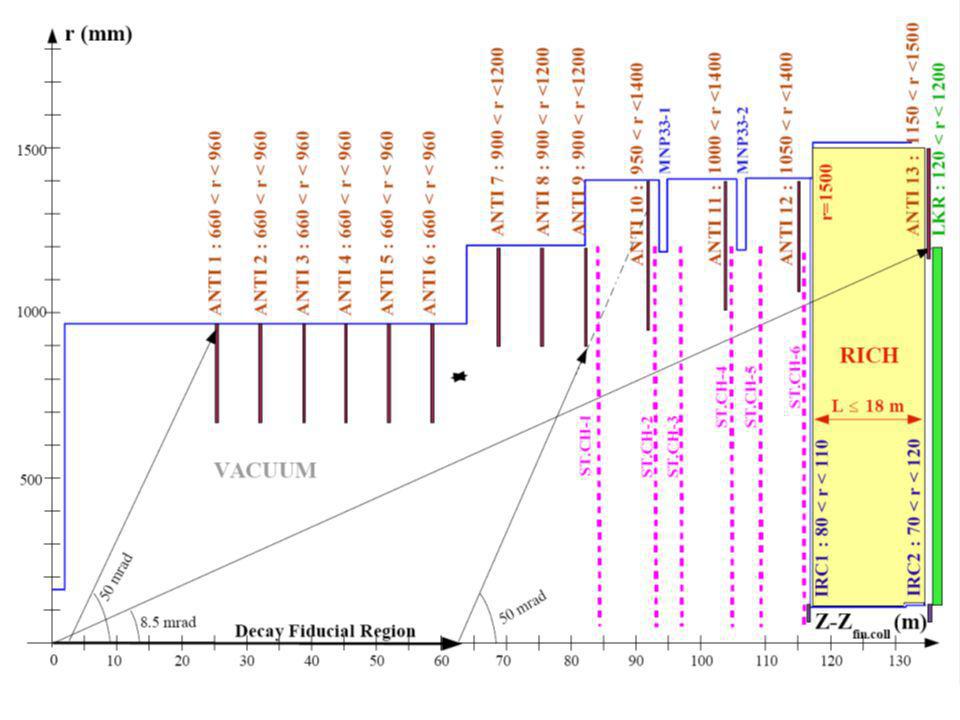
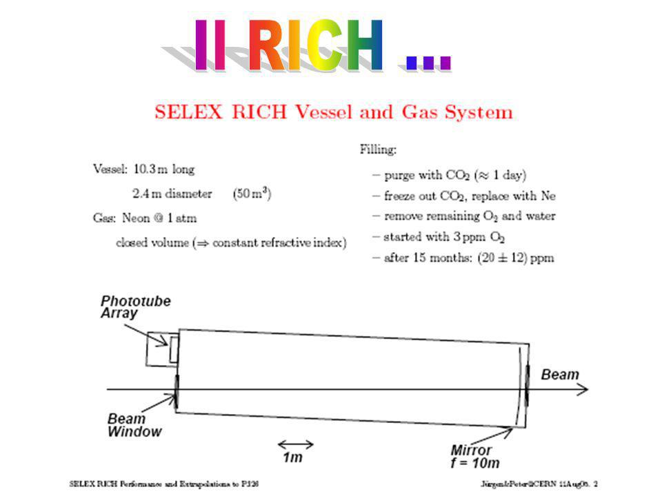
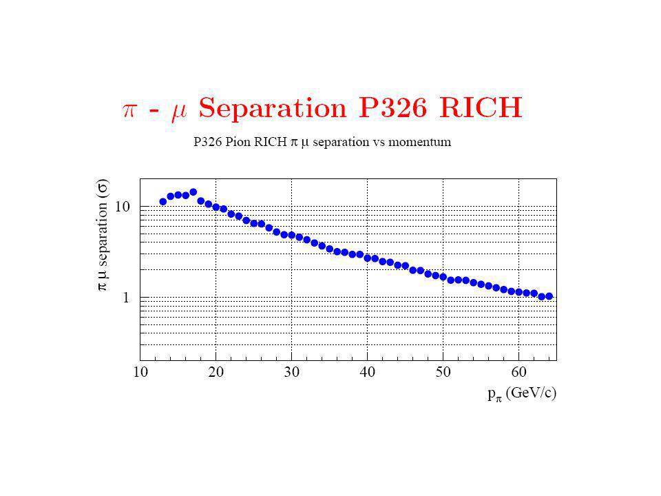
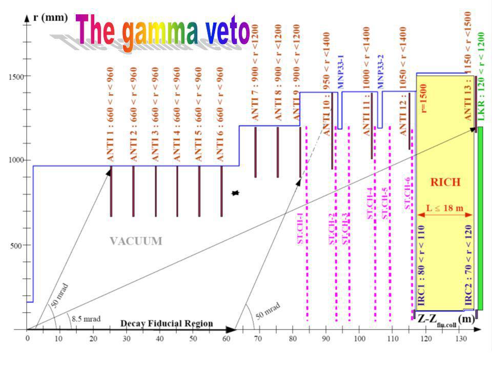
Veto and particle ID RICH (Simulation by Jurgen): 17 m long, 1.0 atm Ne – Veto (Geant4 simulation by Oleg): -veto = 10 5 E rangeInefficiency ANTI < 50 MeV1 (0.5, 1) GeV10 4 > 1 GeV10 5 LKR < 1 GeV1 (1,3) GeV10 4 (3,5) GeV10 4 10 5 > 5 GeV10 5 IRCs SAC All10 6 – Veto: inefficiency parameterization JURGEN
: 17 m long, 1.0 atm Ne – Veto (Geant4 simulation by Oleg): -veto = 10 5 E rangeInefficiency ANTI < 50 MeV1 (0.5, 1) GeV10 4 > 1 GeV10 5 LKR < 1 GeV1 (1,3) GeV10 4 (3,5) GeV > 5 GeV10 5 IRCs SAC All10 6 – Veto: inefficiency parameterization JURGEN")
27
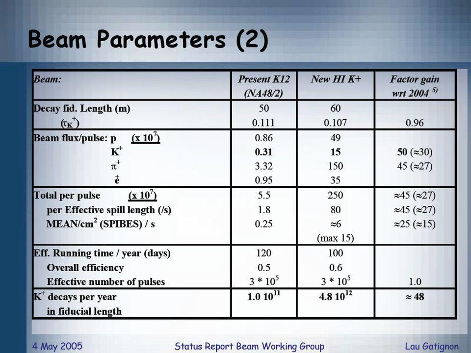
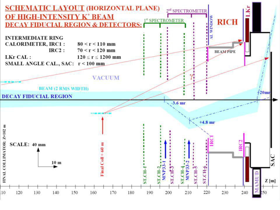
Some general remarks … Kaon Flux: 4.8×10 12 decay/year in the fiducial region Detector Layout as described in the proposal: Straw chambers 5cm inner radius displaced in x, according to the positive beam deflection in the spectrometers Magnets of the double spectrometer: MNP33 – 1 P t kick = 270 MeV/c MNP33 - 2 P t kick = -360 MeV/c All the expected background given per 1 year of data taking

28
Selection (1) Number of tracks 1 positive downstream track (hit in all the 6 chambers) Choice of the upstream track using minimum 2 ( t, cda) Detector geometry Downstream track inside of the detector acceptance: Straws: 10 cm < R track < 85 cm (centered on the hole of the chamber) RICH: 12 cm < R track < 120 cm (both on front and back surfaces) LKr: Octagonal outer shape and R track > 15 cm MAMUD: square shape, 260x260 cm outer, 36x30 cm inner (front and back) Particle ID Not muons in RICH or MAMUD Not electrons in RICH or LKr (LKr with 10 -3 inefficiency of e – ID)
 Number of tracks 1 positive downstream track (hit in all the 6 chambers) Choice of the upstream track using minimum 2 ( t, cda) Detector geometry Downstream track inside of the detector acceptance: Straws: 10 cm < R track < 85 cm (centered on the hole of the chamber) RICH: 12 cm < R track < 120 cm (both on front and back surfaces) LKr: Octagonal outer shape and R track > 15 cm MAMUD: square shape, 260x260 cm outer, 36x30 cm inner (front and back) Particle ID Not muons in RICH or MAMUD Not electrons in RICH or LKr (LKr with inefficiency of e – ID)")
29
Selection (2) Fiducial decay region 5 m < Z vertex < 65 m (from the final collimator, Z vertex defined as the Z coordinate of the point closest to both the tracks) Specific cuts P track /P track < 2.5× (P)/P (against the not gaussian tails) CDA < 0.8 cm (against the tails from the beam pile – up) Kinematics REGION I: 0 < m 2 miss < 0.01 GeV 2 /c 4 REGION II: 0.026 < m 2 miss < 0.068 GeV 2 /c4 Cut on momentum 15 GeV/c < P track < 35 GeV/c
 Fiducial decay region 5 m < Z vertex < 65 m (from the final collimator, Z vertex defined as the Z coordinate of the point closest to both the tracks) Specific cuts P track /P track < 2.5× (P)/P (against the not gaussian tails) CDA < 0.8 cm (against the tails from the beam pile – up) Kinematics REGION I: 0 < m 2 miss < 0.01 GeV 2 /c 4 REGION II: < m 2 miss < GeV 2 /c4 Cut on momentum 15 GeV/c < P track < 35 GeV/c")
30
Acceptance after all the cuts: Acc=(8 ± 2) × 10 6 Same procedure as for + 0 to extract the acceptance Expected events: N(K 2 ) = kaon × BR × Acc × Rich ( ) × MAMUD ( ) = (1.2 ± 0.3) / year – – Region I: 1.1 / year – – Region II: <0.1 / year – – N ngaus ~ 0.4 / year, N pileup ~ 0.8 / year Muon veto inefficiency: MAMUD ( ) = 10 5 (MAMUD) RICH ( ) = 5 × 10 3 (RICH) (conservative) Assumption: MAMUD and RICH rejection inefficiencies independent
 × 10 6 Same procedure as for + 0 to extract the acceptance Expected events: N(K 2 ) = kaon × BR × Acc × Rich ( ) × MAMUD ( ) = (1.2 ± 0.3) / year – – Region I: 1.1 / year – – Region II: <0.1 / year – – N ngaus ~ 0.4 / year, N pileup ~ 0.8 / year Muon veto inefficiency: MAMUD ( ) = 10 5 (MAMUD) RICH ( ) = 5 × 10 3 (RICH) (conservative) Assumption: MAMUD and RICH rejection inefficiencies independent")
31
+ 0 Acceptance after all the cuts: Acc = (1.3 ± 0.1) × 10 4 Assumption: independence between kinematical rejection inefficiency ( kin ) and selection acceptance N I,II = kin ×N sel (Flyo)+N pileup (Flyo) N I,II = Number of expected events in regions I and II after all the cuts N sel (Flyo) = number of events selected in Flyo before the cut on m 2 miss N pileup (Flyo) = number of events in Regions I and II due to the beam pileup Acc = N I,II / N gen (Flyo) Expected events: N( + 0 ) = kaon × BR × Acc × ( 0 ) = (2.7 ± 0.2) / year – – Region I: 1.7 / year – – Region II: 1.0 / year – – N ngaus ~ 0.5 / year, N pileup ~ 2.2 / year Photon veto inefficiency: ( 0 ) = 2 × 10 8
 × 10 4 Assumption: independence between kinematical rejection inefficiency ( kin ) and selection acceptance N I,II = kin ×N sel (Flyo)+N pileup (Flyo) N I,II = Number of expected events in regions I and II after all the cuts N sel (Flyo) = number of events selected in Flyo before the cut on m 2 miss N pileup (Flyo) = number of events in Regions I and II due to the beam pileup Acc = N I,II / N gen (Flyo) Expected events: N( + 0 ) = kaon × BR × Acc × ( 0 ) = (2.7 ± 0.2) / year – – Region I: 1.7 / year – – Region II: 1.0 / year – – N ngaus ~ 0.5 / year, N pileup ~ 2.2 / year Photon veto inefficiency: ( 0 ) = 2 × 10 8")
32
Two body background vs Spibes performances K 2 + 0 Total Spibes ineff (t) Spibes ns 2 body background events
 Spibes ns 2 body background events")
33
Other backgrounds Ke3: Acceptance ~12% (Flyo) 0 ~ 3×10 8 Positron ID: LKr × RICH < 10 3 × 10 3 (conservative) NEGLIGIBLE K 3: Acceptance ~17% (Flyo) 0 ~ 3×10 8 Muon ID: RICH × MAMUD < 10 5 × 10 2 (conservative) NEGLIGIBLE + 0 0 : High suppression from kinematics and veto NEGLIGIBLE
 0 ~ 3×10 8 Positron ID: LKr × RICH < 10 3 × 10 3 (conservative) NEGLIGIBLE K 3: Acceptance ~17% (Flyo) 0 ~ 3×10 8 Muon ID: RICH × MAMUD < 10 5 × 10 2 (conservative) NEGLIGIBLE : High suppression from kinematics and veto NEGLIGIBLE")
34
Signal Acceptance Selection applied on events generated with FF (from CMC) Effects not taken into account: Random veto Accidental loss due to hit multiplicity cuts Straw inefficiency Loss due to cuts in MAMUD for muon ID BR( + )=8×10 11 (SM)
 Effects not taken into account: Random veto Accidental loss due to hit multiplicity cuts Straw inefficiency Loss due to cuts in MAMUD for muon ID BR( + )=8×10 11 (SM)")
35
Signal Acceptance Results REGION I: (4.10 ± 0.03) × 10 -2 REGION II: (12.88 ± 0.05) × 10 -2 Total: (16.98 ± 0.06) × 10 -2 Acceptance normalized in the region: 5 m < Z vertex < 65 m Most important cuts N track =1: cuts 8% of events Geometry: cuts 10% of events Momentum: cuts 50% of events Pile – Up: cuts 12% of events
 × REGION II: (12.88 ± 0.05) × Total: (16.98 ± 0.06) × Acceptance normalized in the region: 5 m < Z vertex < 65 m Most important cuts N track =1: cuts 8% of events Geometry: cuts 10% of events Momentum: cuts 50% of events Pile – Up: cuts 12% of events")
36
Signal and backgrounds / year TotalRegion IRegion II Signal~65~16~49 + 0 2.7±0.21.7±0.21.0±0.1 K 2 1.2±0.31.1±0.3<0.1 K e4 2±2negligible2±2 + + and 3-tracks 1±1negligible1±1 + 0 1.3±0.4negligible1.3±0.4 K 2 0.4±0.10.2±0.1 K e3, K 3 negligible Total bkg9±33.0±0.26±3

37
Results: S/B S/B (Total) = 7.6 ± 2.0 S/B (Region I) = 5.2 ± 1.1 S/B (Region II) = 8.9 ± 3.6 Some S/B dependence on detector parameters uncorrelated errors 80 ps200 ps2% Hodo time resolutionSpibes time resolutionSpibes inefficiency
 = 7.6 ± 2.0 S/B (Region I) = 5.2 ± 1.1 S/B (Region II) = 8.9 ± 3.6 Some S/B dependence on detector parameters uncorrelated errors 80 ps200 ps2% Hodo time resolutionSpibes time resolutionSpibes inefficiency")
39
Beam Line (CERN) CEDAR (CERN) GIGATRACKER (CERN, INFN, Saclay [kabes]) VACUUM TANK (Common fund) ANTI Counters (INFN) STRAW TRACKER (DUBNA, MAINZ) MNP33/2 (Common Fund) CHOD (INFN) RICH (US? + Mexico) LKR (CERN+INFN) MAMUD (INR+Protvino) SAC + IRC (Sofia) Trigger & DAQ (CERN+INFN+?) A. Ceccucci August 31 2005 - Cambridge Tentative sharing of construction responsibility (sept. 05)
![Beam Line (CERN) CEDAR (CERN) GIGATRACKER (CERN, INFN, Saclay [kabes]) VACUUM TANK (Common fund) ANTI Counters (INFN) STRAW TRACKER (DUBNA, MAINZ) MNP33/2 (Common Fund) CHOD (INFN) RICH (US.](http://images.slideplayer.it/2/583930/slides/slide_39.jpg "+ Mexico) LKR (CERN+INFN) MAMUD (INR+Protvino) SAC + IRC (Sofia) Trigger & DAQ (CERN+INFN+ ) A. Ceccucci August Cambridge Tentative sharing of construction responsibility (sept. 05).")
40
ElementCost (MCHF)Comments BEAM LINE0.4Modified K12 line CEDAR0.5Replacement of photon detectors GIGATRACKER2.7 (1.4) Assuming 0.13 m CMOS technology VACUUM1.0Addition of 20 large diffusion pumps ANTI4.2 (4.2)CKM estimate + 40% for the electronics STRAW TRACKER2.46 straw chambers MNP33/22.5(1170 + prolongation of He tank) CHOD0.9 (0.9)MGG-RPC LKR2.0 !!!New supervision system and R/O RICH4.0Indication MAMUD1.5Cost of iron 0.5 MCHF SAC, IRC1 & IRC20.4Shashlik or PbWO 4 Trigger & DAQ1.5 (0.7)L0 HW, L1 SW TOTAL24.0 (7.2)
Comments BEAM LINE0.4Modified K12 line CEDAR0.5Replacement of photon detectors GIGATRACKER2.7 (1.4) Assuming 0.13 m CMOS technology VACUUM1.0Addition of 20 large diffusion pumps ANTI4.2 (4.2)CKM estimate + 40% for the electronics STRAW TRACKER2.46 straw chambers MNP33/22.5( prolongation of He tank) CHOD0.9 (0.9)MGG-RPC LKR2.0 !!!New supervision system and R/O RICH4.0Indication MAMUD1.5Cost of iron 0.5 MCHF SAC, IRC1 & IRC20.4Shashlik or PbWO 4 Trigger & DAQ1.5 (0.7)L0 HW, L1 SW TOTAL24.0 (7.2)")
41
Gigatracker0.7-1.0 M (assumendo 50% sharing) Anticounters2.8-3.4 M Chod 0.5–0.7 M Trigger0.5-0.8 M (assumendo 40% sharing) TOTALE 4.5-5.9 M (Nella proposta sono quotati 7.2 MCHF = 4.8 M )
 Anticounters M Chod 0.5–0.7 M Trigger M (assumendo 40% sharing) TOTALE M (Nella proposta sono quotati 7.2 MCHF = 4.8 M )")
42
Abbiamo, molto schematicamente, due problemi: Politico: Politico: la Collaborazione ha bisogno di rinforzarsi. Ci sono stati notevoli passi in avanti nel 2005, come discusso allinizio, e comunque noi continueremo su questa strada … Tecnico: Tecnico: siamo in grado di installare i rivelatori che ci servono? Per questo abbiamo un programma di R&D per tutti i nuovi rivelatori e per validare quanto resta dei vecchi (il LKr …)
.")
43
Il 27 settembre, verrà presentata allSPSC, insieme alla Proposta P326, una contestuale richiesta di 30 gg di run per il 2006, sulla solita linea di fascio K12, principalmente per - misurare linefficienza di osservazione dei fotoni con il LKr - misurare linefficienza di osservazione dei fotoni con il LKr - misurare il fondo da /K interagenti con il gas residuo - misurare il fondo da /K interagenti con il gas residuo - determinare l'alone del fascio - determinare l'alone del fascio - effettuare i tests necessari sui prototipi dei nuovi rivelatori - effettuare i tests necessari sui prototipi dei nuovi rivelatori (Cedar, hodo, sensori gigatracker …) (Cedar, hodo, sensori gigatracker …)
 (Cedar, hodo, sensori gigatracker …)")
44
R&D sui rivelatori di nostra pertinenza: Hodoscopio Veto dei Veto dei Gigatracker

45
Lidea è quella di usare Glass Multigap RPCs, sullo stile di quanto realizzato in ALICE A questo rivelatore infatti è richiesto di essere efficiente (>99%) e di avere unottima risoluzione temporale (50ps) in modo da ridurre al massimo la possibilità di associazioni accidentali fra il pione di decadimento ed il K che lo origina. FI-PG

46
ALICE detector layout 2 anode and 1 chatode PCB with picup pads 5+5 250 m gaps filled with gas mixture 1 cm honeycombs panel for mechanical stability 96 pads per module readout with 32 flat cable Differential signal send to interface card 13x120 cm 2 area for each module 7x120 cm 2 active area for each module Greater number of gaps Lower HV (+6.5 kV, -6.5 kV) Signal amplitude greater of a factor 2
 Signal amplitude greater of a factor 2")
47
Front-End electronics ALICE has developed for this purpose, fast (1ns peaking time) front-end amplifier/discriminator (NINO). Each NINO can handle 8 channels. The input is low impedance (40-75 ) differential, and the output standard is an open-collector LVDS (Low Voltage Differential Signal). NINO can respond to another signal immediately (few ns) after the end of a previous signal (almost no dead time). On each front end card 3 NINO chip are mounted so the card can handle 24 channels The NINO ASIC bonded to the PCB
 differential, and the output standard is an open-collector LVDS (Low Voltage Differential Signal). NINO can respond to another signal immediately (few ns) after the end of a previous signal (almost no dead time). On each front end card 3 NINO chip are mounted so the card can handle 24 channels The NINO ASIC bonded to the PCB.")
48
MRPC performance Efficiency > 99% Time resol. < 50 ps Test performed with the ALICE TOF rate 50 Hz

49
Rate tests at GIF The MRPC were tested for efficiency up to a rate of 1.6 kHz The performance seem to be stable only using an effective voltage of 11.4 kV The MRPC were tested for time resolution up to a rate of 1.6 kHz The time resolution seem to decrease a little bit The resolution at 1.6 kHz is well above 100 ps This performance are very suitable for P326 New high rate test are mandatory to validate performance up to 5 kHz

50
Ageing test at GIF Irradiation with 710 9 particles/cm 2 The performances seem to remain stable in time The total amount of irradiated charge is equivalent to only 140 days of P326 run:

51
Cathode -10 kV Anode 0 V (-2 kV) (-4 kV) (-6 kV) (-8 kV) Signal electrode We stick as much as we can to the Alice design, however to reduce material, we are planning a single stack layer. The time resolution, according to experts, should go from ~40 ps to ~80 ps G MRPC for P326

52
The new PCB for P326 The PCB design used by ALICE is not suitable for P326: –The connectors on each side introduce too much dead space between two modules –Itis very difficult to bring signals out of the detector using ALICE configuration –The material budget would not be uniform due to connectors and cables We are working on a new PCB layout, assuming –Connectors only at the end of each module –Each module is single-layer

53
Where we are First prototype assembly foreseen in late november Cosmic ray test will be done, hopefully, within 2005 Test of efficiency and time resolution at high rate are mandatory to validate the possible use of such a detector in P326: test envisaged with NA48 test-run facility in 2006. We are now investigating the possibility of performing the rate test, using some existing ALICE modules at some beam facility, to be found.

55
Must achieve inefficiency < 10 -5 to detect photons above 1 GeV, and this has to be tested in 2006. It has also to be evaluated the effect on the inefficiency of the material in front of the calorimeter (RICH, hodoscope, windows, etc) Advantages: –It exists –Homogeneous (not sampling) ionization calorimeter –Very good granularity (~2 2 cm 2 ) –Fast read-out (Initial current, FWHM~70 ns) –Very good energy (~1%, time ~ 300ps and position (~1 mm) resolution Disadvantages –0.5 X 0 of passive material in front of active LKR –The cryogenic control system needs to be updated –Needs a new readout
 Advantages: –It exists –Homogeneous (not sampling) ionization calorimeter –Very good granularity (~2 2 cm 2 ) –Fast read-out (Initial current, FWHM~70 ns) –Very good energy (~1%, time ~ 300ps and position (~1 mm) resolution Disadvantages –0.5 X 0 of passive material in front of active LKR –The cryogenic control system needs to be updated –Needs a new readout.")
56
Large angle vetoes The detector must be able to veto 0 s, with energy in the range 40-65 GeV, at the 10 -8 level. This means that it must possess an average veto power on the single photon of the order 10 -4 Two technologies are to be compared: Tiles a la CKM Spaghetti a la KLOE Extensive Geant4 simulation started to study both solutions as far as punch- through, inefficiency dependence from the hitting angle, energy and position, … are concerned. But also to be compared Costs Mechanical design of the support … LNF, NA, PI, RM1

57
Tile and KLOE geometry 1 mm 1 cm AluminumScintillatorLead 27.75cm 42.5 cm 30 cm 2 /16 29.9 cm Beam Axis 1 cm 1 mm 2.5 m 24 cm

58
The CKM prototype at FNAL Former CKM physicists interested in joining us. A lot of R/D was already done for CKM vetoes. A prototype (2 sectors, 80 layers, 1mm/5mm) exists at FNAL, tested in an electron beam. Results are published: Inefficiency for electrons @ 1.2 Gev/c 3*10 -6 In 2006 we would like to arrange in Frascati a comparative test with it and a KLOE prototype, to be built.
 exists at FNAL, tested in an electron beam. Results are published: Inefficiency for 1.2 Gev/c 3*10 -6 In 2006 we would like to arrange in Frascati a comparative test with it and a KLOE prototype, to be built..")
59
The Protvino prototype –Protvino has the know-how for scintillator production They have bought all the manufacturing equipment for scintillator from Uniplast (in Vladimir) –Extruded scintillator –Molded scintillator –Intended to be used for CKM (Kplus) and KOPIO Interested to collaborate. –A 20 layer prototype already available, –Full prototype under consideration Opportunity to use this facility for P326 Need discussion, inspection, agreement, control, etc..

60
Test con elettroni del prototipo KLOE già iniziati … Presa dati con Elettroni da 480 MeV, alla BTF dei LNF, dal 18 al 22 luglio, in modalità parassita alle normali operazioni per KLOE. Presa dati con Elettroni da 480 MeV, alla BTF dei LNF, dal 18 al 22 luglio, in modalità parassita alle normali operazioni per KLOE.

61
Setup VME DAQ VME DAQ Charge integrating ADC, gate=200 ns Charge integrating ADC, gate=200 ns trigger dal sistema di timing del fascio trigger dal sistema di timing del fascio Fascio ottimizzato: x y 2 mm Bassa intensità: =0.5 ÷1

62
Inefficienza (preliminare !)Soglia Inefficienza E totale 11000 eventi con tag 11000 eventi con tag Tutti Con tag 70 140 210 280350 (MeV) (ADC) Eventi CAVEAT CAVEAT Prototipo realizzato nel 1992, e strumentato su Prototipo realizzato nel 1992, e strumentato su un solo lato Qualche canale mostra un guadagno più basso (accoppiamento ottico guida/fotomoltiplicatore?) Qualche canale mostra un guadagno più basso (accoppiamento ottico guida/fotomoltiplicatore?) I canali non erano equalizzati né calibrati (run di cosmici in corso…) I canali non erano equalizzati né calibrati (run di cosmici in corso…) La Statistica é limitata … La Statistica é limitata … e lanalisi é ancora in corso e lanalisi é ancora in corso
Soglia Inefficienza E totale eventi con tag eventi con tag Tutti Con tag (MeV) (ADC) Eventi CAVEAT CAVEAT Prototipo realizzato nel 1992, e strumentato su Prototipo realizzato nel 1992, e strumentato su un solo lato Qualche canale mostra un guadagno più basso (accoppiamento ottico guida/fotomoltiplicatore ) Qualche canale mostra un guadagno più basso (accoppiamento ottico guida/fotomoltiplicatore ) I canali non erano equalizzati né calibrati (run di cosmici in corso…) I canali non erano equalizzati né calibrati (run di cosmici in corso…) La Statistica é limitata … La Statistica é limitata … e lanalisi é ancora in corso e lanalisi é ancora in corso")
63
Piano di lavoro 2006 Test alla BTF con elettroni e fotoni (quando disponibili): Misura dellinefficienza in funzione di –Energia –Posizione/angolo di impatto (studio degli effetti di bordo) Misura della risoluzione temporale Misura della risoluzione in energia Studio dei segnali –Ottimizzazione dellelettronica di readout –Ottimizzazione del guadagno In particolare, vorremmo poter confrontare i risultati ottenuti sul prototipo CKM e Protvino con quelli avuti su un prototipo a la KLOE da costruire In particolare, vorremmo poter confrontare i risultati ottenuti sul prototipo CKM e Protvino con quelli avuti su un prototipo a la KLOE da costruire. … in modo che, entro il 2006 si possa giungere alla scelta della tecnologia

64
Premessa: Il Gigatracker consta di 2 stazioni di Pixel posizionate nella regione del secondo achromat, dove il fascio viene deviato di - 40mm in direzione verticale e riportato in posizione dopo circa 6 metri. Le due stazioni di pixel dovranno misurare la posizione e il tempo di passaggio delle particelle del fascio. Dalla seconda stazione e da una terza, equipaggiata con una FastTPC (KABES), ci si attende la misura della direzione di tali particelle, minimizzando la deviazione dovuta al multiple scattering. R/O chip SensoreBumpbondingFE-TO(CERN)
, ci si attende la misura della direzione di tali particelle, minimizzando la deviazione dovuta al multiple scattering. R/O chip SensoreBumpbondingFE-TO(CERN).")
65
La dimensione del fascio alle stazioni di pixel e' di circa 36x48mm 2, con un rate massimo di 1.9MHz/mm 2, 0.6MHz/mm 2 in media, e in totale circa 1 GHz, di cui solo circa il 6% sono K +. Dal decadimento del K + in bar non si avra' alcuna informazione sulla posizione del vertice di decadimento (solo il + viene rivelato). Le informazioni dal Gigatracker dovranno permettere la coincidenza di un + visto nel rivelatore (tempo dal hodo e direzione e momento dallo spettrometro) con un K + passato nel GT. Questo impone ai pixel risoluzioni, sia spaziali che temporali, piuttosto stringenti, tali da avere, sulla traccia: t ~ 150ps, p/p <0.4%, ~17 rad mantenendo minimo il materiale posto su fascio (X 0 <<1%). Caratteristiche
. Le informazioni dal Gigatracker dovranno permettere la coincidenza di un + visto nel rivelatore (tempo dal hodo e direzione e momento dallo spettrometro) con un K + passato nel GT. Questo impone ai pixel risoluzioni, sia spaziali che temporali, piuttosto stringenti, tali da avere, sulla traccia: t ~ 150ps, p/p <0.4%, ~17 rad mantenendo minimo il materiale posto su fascio (X 0 <<1%). Caratteristiche.")
66
- Ottimizzazione spessore: 300 m Si: 100 (chip) + 200 (rivelatore) 150 (chip) + 150 (rivelatore) supporto segnale! Da testare: segnale, fragilita', danneggiamento da radiazione (~12 Mrad in 100 gg) fascio rate ~1GHz maggior parte, solo 6.5% 12.32m Pixel 1 6.05m Kabes final collimator, decay volume, detector 87m Ch1 40mm 80.681m from T0 86.731m from T0 Pixel2 99.051 m from T0 204.850m from T0 35000 canali/stazione35000 canali/stazione - Ottimizzazione dimensioni pixel X = 200 (300) m / 1 2 -> X = 58 (87) m, MultSc Si spessore 200 m~13 rad xMSP1 = 13*6.05 ~80 m V pixel size mom resol (P1,P2) ( X2 & xMSP1 )/40mm 200 m (300) = 0.3% (0.4%) H pixel size Angular resol (P2,K3 kab =80 m) (s X & s kab ) /12.3m & MSP1 200 m (300) = 15 rad (16 rad)
 fascio rate ~1GHz maggior parte, solo 6.5% 12.32m Pixel m Kabes final collimator, decay volume, detector 87m Ch1 40mm m from T m from T0 Pixel m from T m from T canali/stazione35000 canali/stazione - Ottimizzazione dimensioni pixel X = 200 (300) m / 1 2 -> X = 58 (87) m, MultSc Si spessore 200 m~13 rad xMSP1 = 13*6.05 ~80 m V pixel size mom resol (P1,P2) ( X2 & xMSP1 )/40mm 200 m (300) = 0.3% (0.4%) H pixel size Angular resol (P2,K3 kab =80 m) (s X & s kab ) /12.3m & MSP1 200 m (300) = 15 rad (16 rad).")
67
Per la realizzazione dell'elettronica di lettura dei rivelatori a pixel si stanno studiando due opzioni tecnologiche: la CMOS 0.25 m e la CMOS 0.13 m. La tecnologia 0.25 m è ben conosciuta e caratterizzata nei suoi aspetti di prestazioni analogiche e di radiation tolerance ed i costi sono relativamente contenuti. Di contro le prestazioni che offre sono nettamente inferiori e queste potrebbero non essere sufficienti per l'esperimento. Inoltre il supporto e l'aggiornamento del design kit per il progetto di circuiti tolleranti alle radiazioni si e` inoltre interrotto nel 2002. La 0.13 m è attualmente in fase di caratterizzazione per quanto riguarda sia le prestazioni analogiche che la tolleranza alle radiazioni. Trattandosi poi di una tecnologia di punta i costi saranno superiori di un fattore ~2 rispetto alla 0.25 mm (2 M invece di 1 M…) R/O chip
 R/O chip.")
68
E per il sensore, da dove si parte? Esperienza: Alice SPD Sensore Si: CANBERRA high resistivity FZ p+ pixel su substrato n spessore 200 m pixel size 50 mx425 m r/o chip CMOS 250nm spessore Si supporto 150 m (nativo 750 m) bump bonding: SnPb VTT Finlandia best of the best yield 99% Le richieste di P326 sul sensore al Si sono: spessore 200 m (min X 0 ) pixel dim 300 m x 300 m OK (risoluzione su P e ) Convenzione INFN-ITC/IRST cfr delibere 8610,8649 Lavorazione gratuita: solo spese materiale es maschere, sensori Non solo business... anche ricerca e su vari substrati (n,p-type) di varia produzione (epi, FZ, CZ...) cfr es Boscardin @ Scuola LNL 4-8/04/2005 Test produzione & lavorazione bb VTT al chip di Alice con aggiunta strutture test ad hoc Vincoli: layout chip Alice
 bump bonding: SnPb VTT Finlandia best of the best yield 99% Le richieste di P326 sul sensore al Si sono: spessore 200 m (min X 0 ) pixel dim 300 m x 300 m OK (risoluzione su P e ) Convenzione INFN-ITC/IRST cfr delibere 8610,8649 Lavorazione gratuita: solo spese materiale es maschere, sensori Non solo business... anche ricerca e su vari substrati (n,p-type) di varia produzione (epi, FZ, CZ...) cfr es Scuola LNL 4-8/04/2005 Test produzione & lavorazione bb VTT al chip di Alice con aggiunta strutture test ad hoc Vincoli: layout chip Alice.")
69
Dove siamo? 3 wafer (200 m-ex300A/B, 200ex600B) sent @ VTT for bb with Alice's chip --> expected back at CERN soon Alice's standard test on the Ladder Diodes and pixel arrays: tests and dicing ---> Legnaro for irradiation studies with protons (bulk damage) - measure V fd, I leak vs fluence and - find equivalent fluence inversion point - monitoring vs time and temperature p+ n n+ Example of n-type inversion on 300 m thick test structures for Alice, R.Wundstorfs thesis 69 Toward the working point in P326... - eq inversion point and V bias --> replacement every xxx days? - cooling (e.g. ATLAS, CMS ~ -8°C : I leak )
 VTT for bb with Alice s chip --> expected back at CERN soon Alice s standard test on the Ladder Diodes and pixel arrays: tests and dicing ---> Legnaro for irradiation studies with protons (bulk damage) - measure V fd, I leak vs fluence and - find equivalent fluence inversion point - monitoring vs time and temperature p+ n n+ Example of n-type inversion on 300 m thick test structures for Alice, R.Wundstorfs thesis 69 Toward the working point in P eq inversion point and V bias --> replacement every xxx days. - cooling (e.g. ATLAS, CMS ~ -8°C : I leak ).")
70
Programma 2006: Sensor: Test on - Alice-like ladders and singles bb at VTT - diodes & structures dicing --> Legnaro, monitoring Investigation on wafer bow: causes and how to reduce it Cooling: investigation just started Chip: R&D ongoing simulation & design first hints if 0.25 m not possible expected by January06 (dimensions, consumption...) If OK --> 2006 build and test a chip with the various functional blocks and architecture options 70
 If OK --> 2006 build and test a chip with the various functional blocks and architecture options 70")
Presentazioni simili


 064825120 - fax.>")


>")


 A.Cristofoli (laureando.>")

>")

 The target is 24 hr/day, threshold 20 hrs/day 5 days a week Target:>")
 2l2 nel canale di decadimento WW (*) 2l2 Dati Spring07 CMSSW_1_3_x 100 pb -1 (47 pagine)>")
