Scaricare la presentazione
La presentazione è in caricamento. Aspetta per favore

1
Principles of Optical Microscopy (LESSON 1)
")
2
Simple microscope… 1/a + 1/b = 1/f M = h(2)/h(1) = b/a d0d0 d 0 =25 cm f=3 cm G v =8.2 Decreasing f???
/h(1) = b/a d0d0 d 0 =25 cm f=3 cm G v =8.2 Decreasing f")
3
The compound microscope F 2ob F 1oc Optical lenght Typically between 10 3 and 10 4

4
A Modern Microscope: Basic Basic Components: Illuminator Condenser Specimen Objective lens Eyepieces (Projection lens) Detector
 Detector")
5
Resolution Wavelength (Nanome ters) Resolution (Microme ters) 360.19 400.21 450.24 500.26 550.29 600.32 650.34 700.37 The resolution of an optical microscope is defined as the shortest distance between two points on a specimen that can still be distinguished by the observer or camera system as separate entities. Resolution (r) = 0.61 /NA
 = 0.61 /NA.")
6
Numerical Aperture Numerical Aperture (also termed Object-Side Aperture) is a value (often symbolized by the abbreviation NA) originally defined by Abbe for microscope objectives and condensers. It is given by the simple expression: Numerical Aperture (NA) = n sin( ) a measure of its ability to gather light and resolve fine specimen detail at a fixed object distance Highly corrected objectives tend to have much larger numerical apertures for the respective magnification NA may vary from 0.04 for low power objectives to 1.3 or 1.4 for high power oil-immersion apochromatic objectives
 = n sin( ) a measure of its ability to gather light and resolve fine specimen detail at a fixed object distance Highly corrected objectives tend to have much larger numerical apertures for the respective magnification NA may vary from 0.04 for low power objectives to 1.3 or 1.4 for high power oil-immersion apochromatic objectives.")
7
Oil-immersion objective The specimen is sandwiched between the microscope slide and cover glass at point P, the aplanatic point of the hemispherical lens element Properly designed oil immersion objective lenses also correct for chromatic defects that are introduced by the first two lens elements, while introducing a minimum amount of spherical aberration

8
How to “ Read ” an Objective WD (working distance) The distance between the Objective front lens and the top of the cover glass NA (numerical aperture) ∞: Infinity corrected tube length
 The distance between the Objective front lens and the top of the cover glass NA (numerical aperture) ∞: Infinity corrected tube length")
9
Obiettivi corretti all’infinito

10
Depth of Field and Depth of Focus Magnification Numerical Aperture Depth of Field ( m) Image Depth (mm) 4x0.1055.50.13 10x0.258.50.80 20x0.405.83.8 40x0.651.012.8 60x0.850.4029.8 100x0.950.1980.0 When considering resolution in optical microscopy, a majority of the emphasis is placed on point-to-point lateral resolution in the plane perpendicular to the optical axis (Figure 1). Another important aspect to resolution is the axial (or longitudinal) resolving power of an objective, which is measured parallel to the optical axis and is most often referred to as depth of field. Axial resolution, like horizontal resolution, is determined only by the numerical aperture of the objective, with the eyepiece merely magnifying the details resolved and projected into the intermediate image plane G.O. Diffraction
 resolving power of an objective, which is measured parallel to the optical axis and is most often referred to as depth of field. Axial resolution, like horizontal resolution, is determined only by the numerical aperture of the objective, with the eyepiece merely magnifying the details resolved and projected into the intermediate image plane G.O. Diffraction.")
11
Depth of Field and Depth of Focus (II)
")
12
Oculari

13
Illuminazione Illuminazione con sorgente a fuoco ( “ critica ” o di Nelson) Sorgente estesa focalizzata dal condensatore sul piano del campione (non c ’ è un collettore) Problema ad avere una sorgente estesa e uniforme Illuminazione di Köhler Sorgente non uniforme focalizzata dal collettore nel FFP del condensatore. Nel piano del campione, l’immagine dell’apertura di campo funge da sorgente uniforme secondaria

14
Coniugate plane sets: Aperture or Illuminating Conjugate Plane Set Field or Image-Forming Conjugate Plane Set Microscope Exit Pupil: Eye Iris Diaphragm, Ramsden Disc, and Eyepoint Retina of the Eye Camera Image Plane Objective Rear Focal Plane (Objective Rear Aperture) Intermediate Image Plane (Eyepiece Fixed Diaphragm) Condenser Aperture Diaphragm (Condenser Front Focal Plane) Specimen Plane (Object Plane) Lamp Filament Field Diaphragm (Field Stop) (Köhler Diaphragm) Illumination system () Illumination system ( Köhler rules )
 Intermediate Image Plane (Eyepiece Fixed Diaphragm) Condenser Aperture Diaphragm (Condenser Front Focal Plane) Specimen Plane (Object Plane) Lamp Filament Field Diaphragm (Field Stop) (Köhler Diaphragm) Illumination system () Illumination system ( Köhler rules )")
15
What is Contrast? Differences in light intensity, phase, polarization, color create image contrast, which allows individual features and details of the specimen to become visible. Contrast is defined as the difference in light intensity between the object and the adjacent background relative to the overall background intensity Percent Contrast = [(I(s) - I(b))] / I(b) x 100%
 - I(b))] / I(b) x 100%.")
16
Contrast Mechanisms: Bright field (low contrast) Phase contrast Differential interference contrast Dark field contrast Polarization microscopy Fluorescence microscopy Vibration microscopy Chemical Selectivity
 Phase contrast Differential interference contrast Dark field contrast Polarization microscopy Fluorescence microscopy Vibration microscopy Chemical Selectivity")
17
Microscopia in campo chiaro

18
Microscopia in campo scuro

19
Dark field images Very concentrate DNA solution See-living protozoo:Dark and Brigth field images

20
Specimen Type Imaging Technique Transmitted Light Transparent Specimens Phase Objects Bacteria, Cells in Glass Containers Phase Contrast Differential Interference Contrast (DIC) Light Scattering Objects Diatoms, Fibers, Hairs, Rheinberg Illumination Darkfield Illumination Phase Contrast and DIC Light Refracting Specimens Colloidal Suspensions Phase Contrast Dispersion Staining DIC Amplitude Specimens Stained Tissue Brightfield Illumination Fluorescent Specimens Fluorochrome-Stained Sections Fluorescence Illumination Birefringent Specimens Liquid Crystals Polarized Illumination Reflected Light Specular (Reflecting) Surface Polished Metallurgical Samples Brightfield Illumination Phase Contrast, DIC Darkfield Illumination Diffuse (Non-Reflecting) Surface Thin and Thick Films Brightfield Illumination Phase Contrast, DIC Darkfield Illumination Amplitude Surface Features Dyed Fibers Brightfield Illumination Darkfield Illumination Birefringent Specimens Mineral Thin Sections Polarized Illumination Fluorescent SpecimensFluorescence Illumination
 Light Scattering Objects Diatoms, Fibers, Hairs, Rheinberg Illumination Darkfield Illumination Phase Contrast and DIC Light Refracting Specimens Colloidal Suspensions Phase Contrast Dispersion Staining DIC Amplitude Specimens Stained Tissue Brightfield Illumination Fluorescent Specimens Fluorochrome-Stained Sections Fluorescence Illumination Birefringent Specimens Liquid Crystals Polarized Illumination Reflected Light Specular (Reflecting) Surface Polished Metallurgical Samples Brightfield Illumination Phase Contrast, DIC Darkfield Illumination Diffuse (Non-Reflecting) Surface Thin and Thick Films Brightfield Illumination Phase Contrast, DIC Darkfield Illumination Amplitude Surface Features Dyed Fibers Brightfield Illumination Darkfield Illumination Birefringent Specimens Mineral Thin Sections Polarized Illumination Fluorescent SpecimensFluorescence Illumination")
21
Phase Contrast Microscopy Invented by Zernike's in 1934 (Physics Nobel prize in 1953) Translate minute variations in light phase into corresponding changes in amplitude BASED on Abbe theory of image formation Amplitude and phase objects
 Translate minute variations in light phase into corresponding changes in amplitude BASED on Abbe theory of image formation Amplitude and phase objects")
22
Amplitude objects: they are composed by different absorbing parts Phase objects: trasparent to visible light parts with different refraction index

23
Living cells in Brightfield and Phase- Contrast

24
Teoria di Abbe

25
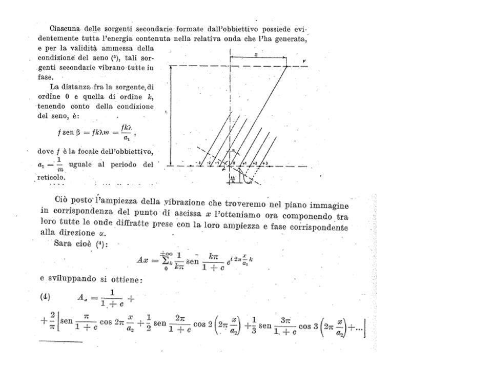
Per esemplificare la teoria di Abbe, è possibile studiare il caso di un oggetto avente particolari requisiti di regolarità: il reticolo di ampiezza Il meccanismo della formazione di immagini per un oggetto qualsiasi è sostanzialmente lo stesso, dal momento che è sempre possibile analizzare in serie di Fourier le deformazioni dell’onda luminosa prodotta dall’oggetto

28
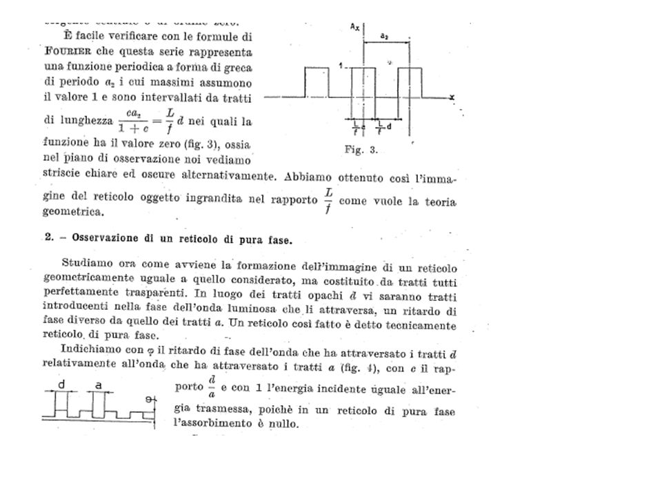
Per ottener l’immagine nel piano oggetto del reticolo di fase, bisogna effettuare il quadrato della precedente espressione. E’ facile verificare che l’illuminamento nel piano immagine è circa costante, ossia il reticolo di fase non produce contrasto.

33
PC microscope Optical Train A phase plate is mounted in or near the objective rear focal plane Each objective has its own codenser annulus. Typically, to help its correct positioning, an anular telescope is provided by the manifacturer. This telescope should be temporanery inserted in one of the two ordinary microscope oculars.

34
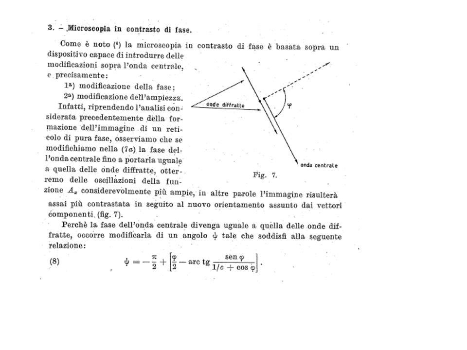
Onda P: attraversa il campione senza subire diffrazione, non incontrando nel suo cammino oggetti micrometrici che producono diffrazione. Quando invece ciò avviene, l’onda P subisce diffrazione, dando luogo alle onde S e D, ossia P=S+D Onda S: onda diffratta da microstrutture del campione, di ordine zero (max principale). La sua ampiezza è prossima a quella dell’onda P, e, rispetto a quest’ultima, è solo leggermente sfasata per effetto dell’attraversamento del campione. Onda D: onda diffratta di ordine superiore. La sua ampiezza è molto minore rispetto all’onda P, ed è sfasata rispetto di λ/4 (π/2 ) rispetto a P. Nel microscopio a contrasto di fase, la lamina di fase induce un cambiamento di fase nell’onda S di ±π/2, oltre ad attenuarne l’ampiezza per aumentare il contrasto (Nel microscopio in campo scuro l’onda S è completamente eliminata)
. La sua ampiezza è prossima a quella dell’onda P, e, rispetto a quest’ultima, è solo leggermente sfasata per effetto dell’attraversamento del campione. Onda D: onda diffratta di ordine superiore. La sua ampiezza è molto minore rispetto all’onda P, ed è sfasata rispetto di λ/4 (π/2 ) rispetto a P. Nel microscopio a contrasto di fase, la lamina di fase induce un cambiamento di fase nell’onda S di ±π/2, oltre ad attenuarne l’ampiezza per aumentare il contrasto (Nel microscopio in campo scuro l’onda S è completamente eliminata).")
35
Positive and negative PC Systems negative phase contrast positive phase contrast

36
Troubles… Two very common effects in phase contrast images are the characteristic halo and shade-off contrast patterns HALO: the circular phase-retarding (and neutral density) ring located in the objective phase plate also transmits a small degree of diffracted light from the specimen SHADE-OFF: the intensity of images produced by a phase contrast microscope does not always bear a simple linear relationship to the optical path difference produced by the specimen
 ring located in the objective phase plate also transmits a small degree of diffracted light from the specimen SHADE-OFF: the intensity of images produced by a phase contrast microscope does not always bear a simple linear relationship to the optical path difference produced by the specimen")
37
Polarization microscopy

38
DIC microscopy A traditional differential interference microscope optical system contains a polarizer located before the condenser and an analyzer (a second polarizer) inserted into the pathway above the objective, usually in an intermediate tube or combined in the frame with the objective Nomarski prism. Positioned behind the objective in the optical pathway is a second Nomarski prism (usually housed in an adjustable sliding frame), which is utilized to recombine the sheared wavefronts in the conjugate plane of the rear aperture after they have been collected and focused by the objective.
, which is utilized to recombine the sheared wavefronts in the conjugate plane of the rear aperture after they have been collected and focused by the objective..")
39
Total effect: Bright object on a dark background a)Mouthparts of a blowfly b)Surface defects in a ferrosilicate alloy Drawback: each objectice needs an its own Wallaston prism couple
Mouthparts of a blowfly b)Surface defects in a ferrosilicate alloy Drawback: each objectice needs an its own Wallaston prism couple")
40
The de Sénarmont DIC Optical System

41
Introduction to Fluorescence Microscopy The absorption and subsequent re-radiation of light by organic and inorganic specimens is typically the result of well-established physical phenomena described as being either fluorescence or phosphorescence

42
Fluorescence microscopy

43
Wild Field Fluorescence Microscopy

44
Just an example…..

45
Fading, Quenching, and Photobleaching The occurrence of photobleaching is exploited in a technique known as fluorescence recovery after photobleaching (FRAP), A related technique, known as fluorescence loss in photobleaching (FLIP), is employed to monitor the decrease of fluorescence in a defined region lying adjacent to a photobleached area.
, A related technique, known as fluorescence loss in photobleaching (FLIP), is employed to monitor the decrease of fluorescence in a defined region lying adjacent to a photobleached area.")
46
Confocal microscopy Optical sectioning

Presentazioni simili