Scaricare la presentazione
La presentazione è in caricamento. Aspetta per favore

1
Fotomoltiplicatori

2
Un po’ di storia Quando si inizia a quantificare la luminosità delle stelle? Ipparco da Nicea, uno dei più importanti astronomi dell’antichità, nel II sec A.C. classifica le stelle in 6 grandezze a seconda della loro luminosità. Assegna 1 alle 20 stelle più brillanti, 2 alle successive e così via. Gran parte del suo lavoro e’ perso nella distruzione della biblioteca di Alessandria (642 D.C.) I. descrive le costellazioni e la posizione esatta di varie stelle, costruì molti strumenti per osservazioni ad occhio nudo tra cui il primo prototipo di astrolabio, migliorato nel III sec dagli astronomi arabi e portato in Europa nel X secolo Questa classificazione fu in seguito adottata da Tolomeo e si e’ perpetuata fino ad oggi (estesa a valori negativi Sirio -1.5, Venere -4.4, luna piena -12.6) Magnitudo e’ scala logaritmica, 1 unità di differenza rappresenta un rapporto di 2,5 volte l’intensità luminosa
 I. descrive le costellazioni e la posizione esatta di varie stelle, costruì molti strumenti per osservazioni ad occhio nudo tra cui il primo prototipo di astrolabio, migliorato nel III sec dagli astronomi arabi e portato in Europa nel X secolo. Questa classificazione fu in seguito adottata da Tolomeo e si e’ perpetuata fino ad oggi (estesa a valori negativi Sirio -1.5, Venere -4.4, luna piena -12.6) Magnitudo e’ scala logaritmica, 1 unità di differenza rappresenta un rapporto di 2,5 volte l’intensità luminosa.")
3
Fotometria Misurazione dell'intensità, della radiazione elettromagnetica di un oggetto astronomico (magnitudine). Limitazione da agitazione atmosferica e luce diffusa dal cielo. Spettrofotometria Non solo misura dell’intensità, ma anche della distribuzione spettrale della radiazione Fotometria visuale (occhio) fotografica (lastre) fotoelettrica (PMT, effetto fotoelettrico + amplificazione) CCD
. Limitazione da agitazione atmosferica e luce diffusa dal cielo. Spettrofotometria. Non solo misura dell’intensità, ma anche della distribuzione spettrale della radiazione. Fotometria. visuale (occhio) fotografica (lastre) fotoelettrica (PMT, effetto fotoelettrico + amplificazione) CCD.")
4
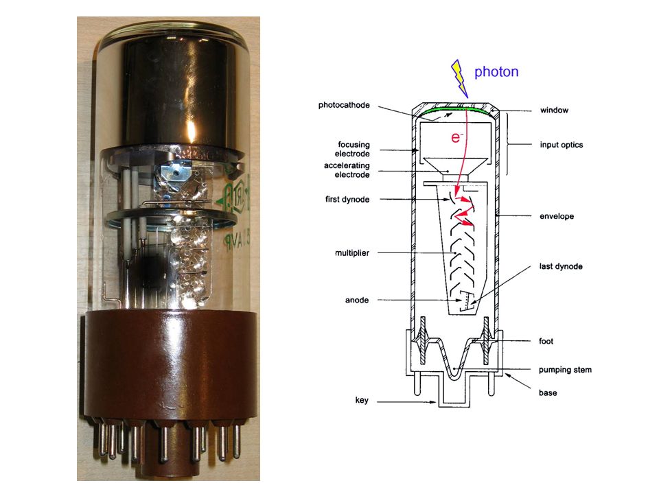
Photo Multiplier Tube Anode Photo Cathode Dynodes Photon-to-Electron Converting Photo-Cathode Dynodes with secondary electron emission Typical gain Transient time spread 200 ps

7
Il PMT è un dispositivo con una risposta temporale molto rapida, per ottimizzare la quale vengono studiate le caratteristiche geometriche della finestra di ingresso, della disposizione dei dinodi ecc. Inoltre la risposta temporale migliora con il quadrato della tensione di alimentazione ALCUNE DEFINIZIONI ESEMPIO DI IMPULSO DI USCITA

8
Transit Time (TT) : intervallo di tempo tra l’arrivo di un impulso luminoso sul catodo e il corrispondente impulso di corrente sull’anodo (≈ qualche decina di ns) Transit Time Spread (TTS) : rappresenta la fluttuazione del TT di ogni impulso di fotoelettrone, quando il fotocatodo è completamente illuminato (solitamente FWHM), determina la risoluzione temporale del PMT valori tipici: TT ~ ns; TTS < ns; rise time ~ 1-2 ns Esempio di TTS
 : rappresenta la fluttuazione del TT di ogni impulso di fotoelettrone, quando il fotocatodo è completamente illuminato (solitamente FWHM), determina la risoluzione temporale del PMT. valori tipici: TT ~ ns; TTS < ns; rise time ~ 1-2 ns. Esempio di TTS.")
9
Electron emission Thermoionic emission Secondary emission
Application of heat allows electrons to gain enough energy to escape Secondary emission Electrons impact a material with sufficient energy to 'knock' additional electrons from the surface. Generally, one electron gives rise to several secondary electrons Field emission A strong external electric field pulls the electron out of the material Photoelectric effect emission of electrons from matter upon the absorption of sufficiently high-frequency electromagnetic radiation, such as ultraviolet radiation or x-rays Interactions of photons: photoelectric effect, Compton scattering, pair production

10
The Photoelectric Effect
Über einen die Erzeugung und Verwanlung des Lichtes betreffenden heuristischen Gesisichtspunkt; von A. Einstein; Bern, den 18. März 1905, Annalen der Physik 17(1905): (ref. M. Planck, Ann. d. Phys. 4, p ) Only by reluctantly introducing a radical new assumption into his mathematics could Planck attain the correct formula. The assumption was that the energy of the radiation does not act continuously, as one would expect for waves, but exerts itself in equal discontinuous parcels, or "quanta," of energy. In essence Planck had discovered the quantum structure of electromagnetic radiation. But Planck himself did not see it that way; he saw the new assumption merely as a mathematical trick to obtain the right answer. Its significance remained for him a mystery. Encouraged by his brief but successful application of statistical mechanics to radiation in 1904, in 1905 Einstein attempted to resolve the duality of atoms and waves by demonstrating that part of Planck's formula can arise only from the hypothesis that electromagnetic radiation behaves as if it actually consists of individual "quanta" of energy. The continuous waves of Maxwell's equations, which had been confirmed experimentally, could be considered only averages over myriads of tiny light quanta, essentially "atoms" of light. At first Einstein believed that the light-quantum hypothesis was merely "heuristic": light behaved only as if it consisted of discontinuous quanta. But in a brilliant series of subsequent papers in 1906 and 1907, Einstein used his statistical mechanics to demonstrate that when light interacts with matter, Planck's entire formula can arise only from the existence of light quanta—not from waves. From this, the following equation results: Ekinetic = h f – W Ekinetic maximal kinetic energy of an emitted electron h Planck constant (6.626 10-34 Js) f frequency W work function David Cassidy, Einstein and Our World
: (ref. M. Planck, Ann. d. Phys. 4, p ) Only by reluctantly introducing a radical new assumption into his mathematics could Planck attain the correct formula. The assumption was that the energy of the radiation does not act continuously, as one would expect for waves, but exerts itself in equal discontinuous parcels, or quanta, of energy. In essence Planck had discovered the quantum structure of electromagnetic radiation. But Planck himself did not see it that way; he saw the new assumption merely as a mathematical trick to obtain the right answer. Its significance remained for him a mystery. Encouraged by his brief but successful application of statistical mechanics to radiation in 1904, in 1905 Einstein attempted to resolve the duality of atoms and waves by demonstrating that part of Planck s formula can arise only from the hypothesis that electromagnetic radiation behaves as if it actually consists of individual quanta of energy. The continuous waves of Maxwell s equations, which had been confirmed experimentally, could be considered only averages over myriads of tiny light quanta, essentially atoms of light. At first Einstein believed that the light-quantum hypothesis was merely heuristic : light behaved only as if it consisted of discontinuous quanta. But in a brilliant series of subsequent papers in 1906 and 1907, Einstein used his statistical mechanics to demonstrate that when light interacts with matter, Planck s entire formula can arise only from the existence of light quanta—not from waves. From this, the following equation results: Ekinetic = h f – W. Ekinetic maximal kinetic energy of an emitted electron h Planck constant (6.626 10-34 Js) f frequency W work function. David Cassidy, Einstein and Our World.")
11
Photoelectric effect Exposing a metallic surface to electromagnetic radiation above the threshold frequency (specific to surface and material), photons are absorbed and current is produced. No electrons are emitted for radiation below threshold frequency (electrons are unable to gain sufficient energy to overcome the electrostatic barrier presented by the termination of the crystalline surface) By conservation of energy, the photon energy is absorbed by the electron and, if sufficient, the “photoelectron” can escape from the material with a finite kinetic energy. A single photon can only eject a single electron, as the energy of one photon may only be absorbed by one electron Threshold effect. Wave-particle duality
, photons are absorbed and current is produced. No electrons are emitted for radiation below threshold frequency (electrons are unable to gain sufficient energy to overcome the electrostatic barrier presented by the termination of the crystalline surface) By conservation of energy, the photon energy is absorbed by the electron and, if sufficient, the photoelectron can escape from the material with a finite kinetic energy. A single photon can only eject a single electron, as the energy of one photon may only be absorbed by one electron. Threshold effect. Wave-particle duality.")
12
The photoelectric effect
3-step process: absorbed g’s impart energy to electrons (e) in the material; energized e’s diffuse through the material, losing part of their energy; e’s reaching the surface with sufficient excess energy escape from it; ideal photo-cathode (PC) must absorb all g’s and emit all created e’s (Photonis) g e- Energy-band model in semi-conductor PC Band gap EG Electron affinity EA Photoemission threshold Wph Optical window Semi-transparent PC Vacuum Opaque PC Substrate g energy Eg h from T. Gys, Academic Training, 2005
 in the material; energized e’s diffuse through the material, losing part of their energy; e’s reaching the surface with sufficient excess energy escape from it; ideal photo-cathode (PC) must absorb all g’s and emit all created e’s. (Photonis) g. e- Energy-band model in semi-conductor PC. Band gap EG. Electron affinity EA. Photoemission threshold Wph. Optical window. Semi-transparent PC. Vacuum. Opaque PC. Substrate. g energy Eg. h. from T. Gys, Academic Training,")
13
Risposta spettrale del fotocatodo quotata in termini di:
Sensibilità luminosa (S,A/W) (corrente fotoelettrica catodica)/(potenza luminosa incidente) Efficienza Quantica (QE,%) (numero fotoelettroni emessi al catodo)/(numero fotoni incidenti)
 (corrente fotoelettrica catodica)/(potenza luminosa incidente) Efficienza Quantica (QE,%) (numero fotoelettroni emessi al catodo)/(numero fotoni incidenti)")
14
Photocathode Negatively charged electrode coated with a photosensitive compound. When struck by light, electrons are emitted due to the photoelectric effect Plain metallic cathode exhibits photoelectric properties, but specialized coating greatly increases the effect. A photocathode usually consists of alkali metals with very low work functions The coating releases electrons much more readily than the underlying metal, allowing it to detect the low-energy photons in infrared radiation. To facilitate the passage of light the photosensitive material is deposited on a thin layer on the inside of the PM window (quartz, UV transmitting (acrylic) glass, synthetic silica)
 glass, synthetic silica)")
15
What is Secondary Electron Emission ?
Approximately the same as the Photo Electric Effect. On electron impact, energy is transferred directly to the electrons in the secondary electron emission material allowing a number of secondary electrons to escape. Since the conducting electrons in metals hinder this escape, insulators and semiconductors are used. Materials in common use are: Ag/Mg, Cu/Be and Cs/Sb. Use has also been made of negative affinity materials as dynodes, in particular GaP. Focusing collection efficiency (#e- 1st dynode) / (#e- photocathode) ~ 80%
 / (#e- photocathode) ~ 80%")
16
Schema elettrico di un fotomoltiplicatore (partitore resistivo) e circuito equivalente
Impulso di corrente dal PM convertito in impulso di tensione con RL verso terra R C

17
Stabilizzazione G: guadagno = (carica all’anodo)/(unita’ di carica emessa dal fotocatodo). Dipende da N e δ; G ~ con 8-14 stadi δ: fattore di emissione secondaria (~2-4) N: numero di dinodi (~10-14) Vd: potenziale tra dinodi V: tensione anodo-catodo A dipende da materiale e geometria, α~ Se N~10, una variazione ~ 0.1% in V produce una variazione ~1% in G => necessaria alimentazione stabilizzata e condizioni operative poco dipendenti da tensione applicata (plateau)
 N: numero di dinodi (~10-14) Vd: potenziale tra dinodi. V: tensione anodo-catodo. A dipende da materiale e geometria, α~ Se N~10, una variazione ~ 0.1% in V produce una variazione ~1% in G => necessaria alimentazione stabilizzata e condizioni operative poco dipendenti da tensione applicata (plateau)")
18
Distribuzione di carica raccolta all’anodo (Hamamatsu M16 e M64)
Linearità: carica raccolta all’anodo proporzionale al numero di fotoni incidenti. M16: piedistallo (no γ) a ~80, 1 fotoelettrone a ~ 220, 2 fotoelettroni a ~ 370. M64: migliore risoluzione, picchi più stretti e distinti Il massimo contributo alle fluttuazioni della moltiplicazione di e- e’ dovuto ai primi stadi di moltiplicazione (si aumenta δ per ridurle)
 a ~80, 1 fotoelettrone a ~ 220, 2 fotoelettroni a ~ 370. M64: migliore risoluzione, picchi più stretti e distinti. Il massimo contributo alle fluttuazioni della moltiplicazione di e- e’ dovuto ai primi stadi di moltiplicazione (si aumenta δ per ridurle)")
19
Passing tracks (left) Single photoelectron signals (right)
 Single photoelectron signals (right)")
Presentazioni simili


 È basata sulla uguaglianza dei momenti delle forze a destra ed a sinistra,>")
 È basata sulla uguaglianza dei momenti delle forze a destra ed a sinistra,>")
 (Hz) El free El bound Thomson Rayleigh ' ' Scattering E.M. Radiation vs electrons.>")


