Scaricare la presentazione
La presentazione è in caricamento. Aspetta per favore

1
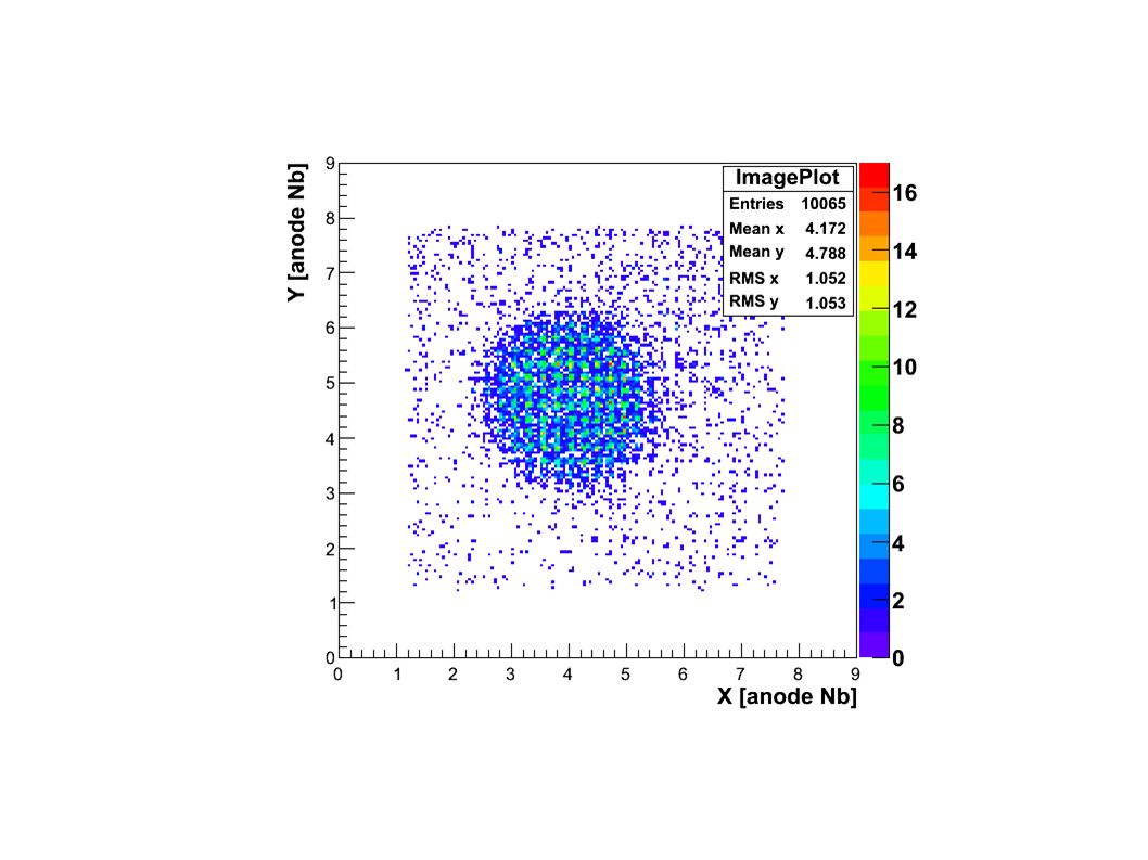
Dopo una prima fase di studi preliminari, ho scelto di operare alle seguenti condizioni: ● HV = -980V ● hold1_delay = 10 ns ● C_feedback = 900 fC (non influisce molto, ma un pò meglio di 300 fC e 600 fC) ● C_buffer = 0 Si osservano I seguenti picchi: autoradiazione 138 La (37 keV), fluorescenza del W (59 keV), 57 Co (122 keV). L'immagine è ottenuta sul picco del 57 Co (finestra energetica mostrata nello spettro)
.")
2
Confronto del “Delay Scan” con la Documentazione di MAROC3 La nostra curva (sinistra) va confrontata con la curva blu della documentazione (destra). Nel nostro caso iniettiamo carica negativa, quindi la curva è invertita. La differenza di circa 50 ns nella posizione del primo picco è dovuta alla differente linea interna di ritardi (per la nostra applicazione serve il trigger interno). Per la stessa ragione non possiamo esplorare la regione 250 ns – 540 ns che quindi è presente solo nella figura di destra. L'accordo risulta essere molto buono, anche se non perfetto
. Per la stessa ragione non possiamo esplorare la regione 250 ns – 540 ns che quindi è presente solo nella figura di destra. L accordo risulta essere molto buono, anche se non perfetto.")
3
Carica iniettata 2 pC. Si osserva una perdita di linearità a GAIN = 1.5

4
La risoluzione energetica relativa raggiunge un valore ottimale con Gain = 1.25. Il valore ottenuto corrisponde al valore atteso dallo scintillatore (LaBr 3 (Ce) con pareti assorbenti)
 con pareti assorbenti).")
5
GAIN = 48

6
PROBLEMA: Lo slow shaper, o comunque qualcosa tra preamplificatore e ADC, mostra un guadagno almeno dieci volte inferiore a quello dichiarato per MAROC3. RISOLTO TBD: ● Test con impulsatore di carica FATTO ● Controllare il rivelatore, fare una mappa di correzione di uniformità (guadagni H8500) ● Passare agli MPPC FATTO, CON S11064 E S12642 ● Confronto diretto con H8500 ENTRO 7 GG ● Ripetere misure con NaI(Tl) aumentando C_buffer di MAROC ENTRO 10 GG
 ● Passare agli MPPC FATTO, CON S11064 E S12642 ● Confronto diretto con H8500 ENTRO 7 GG ● Ripetere misure con NaI(Tl) aumentando C_buffer di MAROC ENTRO 10 GG.")
7
Rumore complessivo (somma su tutti i 64 ingressi = 21 canali di ADC, corrispondenti a circa 50 fC, valore abbastanza consistente con le specifiche. Il nostro segnale è circa 10 pC quindi S/N = 200. In altri termini, la risoluzione energetica potrebbe arrivare a < 2% FWHM

8
Energy resolution 12% FWHM (limite dello scintillatore) Risultato riprodotto per diversi valori di guadagno del preamplificatore di MAROC3
 Risultato riprodotto per diversi valori di guadagno del preamplificatore di MAROC3")
9
Linearità di risposta in carica (fino a 1.5 pC/ch con nuova configurazione di MAROC3) Charge (pC x 100) ADC Amplitude (pedestal subtracted) La linearità con la nuova configurazione è confrontabile con quella ottenuta con la configurazione “attenuante”. La linearità non sembra così buona come da datasheet (<2% fino a 3 pC) ma comunque soddisfacente: 10-15% a 3 pC
 ma comunque soddisfacente: 10-15% a 3 pC.")
10
Hold delay [ns] HOLD DELAY PER I DIVERSI SEGNALI Impulsatore di caricaLaBr 3 (Ce) NaI(Tl ) Picco a 15 ns Picco a 40 ns Massimo a circa 150 ns Massimo a circa 110 ns LYSO
![Hold delay [ns] HOLD DELAY PER I DIVERSI SEGNALI Impulsatore di caricaLaBr 3 (Ce) NaI(Tl ) Picco a 15 ns Picco a 40 ns Massimo a circa 150 ns Massimo a circa 110 ns LYSO](http://images.slideplayer.it/41/11416761/slides/slide_10.jpg "Hold delay [ns] HOLD DELAY PER I DIVERSI SEGNALI Impulsatore di caricaLaBr 3 (Ce) NaI(Tl ) Picco a 15 ns Picco a 40 ns Massimo a circa 150 ns Massimo a circa 110 ns LYSO")
11
Anche selezionando una regione di circa 1 cm 2 in diversi punti non si ottiene una risoluzione migliore di 25% FWHM => Peaking Time dello Slow Shaper?

12
Facendo una misura con sorgente collimata l'immagine è soddisfacente, ma si confermano le perplessità sulla risoluzione energetica

13
Silicon Photomultiplier Finora le misure sono state fatte con H8500. Ora passiamo agli MPPC S11064-050 e S12642-050

14
S11064, BIAS = 70.8 V (Vop = 71.2 V) “MATCHING” LYSO PIXELLATED SCINTILLATOR, 122 keV Gamma Irradiation The scintillator is designed to match the sensor pixel by pixel. By shifting the scintillator half a pixel left and up, the imaging capabilities is tested by using the charge centroid method. Also the external pixels are detected.

15
S11064, BIAS = 70.8 V (Vop = 71.2 V) “MATCHING” LYSO PIXELLATED SCINTILLATOR, 122 keV Gamma Irradiation If the scintillator is properly positioned, then the 16 pixels are perfectly identified. Here there is still a small (<1mm) horizontal shift (and very small rotation) detected by the photosensor, anyway all the pixel are reconstructed in the image. Energy Resolution is about 30% FWHM
 horizontal shift (and very small rotation) detected by the photosensor, anyway all the pixel are reconstructed in the image. Energy Resolution is about 30% FWHM.")
16
S11064, BIAS = 70.8 V (Vop = 71.2 V) “MATCHING” LYSO PIXELLATED SCINTILLATOR, 122 keV Gamma Irradiation If the scintillator is properly positioned, then the 16 pixels are perfectly identified. However, MAROC gain has to be reduced since the full charge is collected by a single channel.

17
S11064, BIAS = 71.4 V (Vop = 71.2 V) “MATCHING” LYSO PIXELLATED SCINTILLATOR, 122 keV Gamma Irradiation If the scintillator is properly positioned, then the 16 pixels are perfectly identified. However, MAROC gain has to be reduced since the full charge is collected by a single channel. Energy Resolution is still about 30% FWHM

18
S11064, BIAS = 71.0 V (Vop = 71.2 V) “MATCHING” LYSO PIXELLATED SCINTILLATOR, 122 keV Gamma Irradiation 2 mm thick glass in introduced between LYSO and S11064. Pixel Identification and Energy Resolution gets worse as expected. Position and Shape of the pixels show the good image performances of the S11064 (the scintillator is not perfectly positioned, there is about 1 mm shift toward left side)
.")
19
S11064

20
S12642, BIAS = 68.4 V (Vop = 68.6 V) SAME LYSO SCINTILLATOR, 122 keV Gamma Irradiation S12642 shows better energy resolution than S11064. However the image quality can not be directly compared due to the different sizes of the two sensors. For example, the pixel in the left upper corner cannot be detected using S12642 because it is completely out of the active area

21
S12642

22
122 keV 22% FWHM

23
CONFRONTO DIRETTO S12642 - H8500, SCINTILLATORE LYSO S12642 H8500 Energy Resolution = 20%

24
C_buffer = 0 C_buffer = 3.75 pF LYSO SCINTILLATOR, MAROC SHAPER OUTPUT C_buffer = 0 DELAY SCAN LYSO WITH S12642

25
C_buffer = 0 C_buffer = 3.75 pF NaI(Tl) SCINTILLATOR, MAROC SHAPER OUTPUT
 SCINTILLATOR, MAROC SHAPER OUTPUT")
27
Energy Resolution 30% FWHM C_buffer = 0C_buffer = 3.75 pF MA ANCHE CON IL LYSO HO LA STESSA RISOLUZIONE PER ENTRAMBI I VALORI DI C_Buffer

28
Matrice di NaI(Tl), S12642 @ 68.5V C_buffer = 0.5pF, C_feedback = 2.1pF
, 68.5V C_buffer = 0.5pF, C_feedback = 2.1pF")
29
Matrice di NaI(Tl), H8500 @ 970V C_buffer = 0 pF, C_feedback = 2.1pF Energy Resolution 15% FWHM
, 970V C_buffer = 0 pF, C_feedback = 2.1pF Energy Resolution 15% FWHM")
Presentazioni simili


 0.8 mm pitch M = 2, FoV = 25×25 mm 2 50×50 mm 2 LaBr 3 (Ce) 4 mm thick, 3 mm thick window M = 2, FoV = 25×25 mm 2 50×50 mm 2 CsI(Na)>")


 Unità Responsabile: Cosenza Unità Coinvolte: Cosenza - Bologna.>")


