Scaricare la presentazione
La presentazione è in caricamento. Aspetta per favore

1
Produzione del chip standard cell AMchip03 Per SVT a CDF Breve descrizione dei tests del prototipo e risultati 1.il chip funziona (up to now) 2.ma yield e’ basso 3.37% perfetti, ~55-60% perfetti+ “quasi” perfetti Descrizione dell’ upgrade AM++ e sua flessibilita’ Descrizione diverse possibilita’ di produzione e loro costi Servono almeno 70 kE aggiuntivi
 2.ma yield e’ basso 3.37% perfetti, ~55-60% perfetti+ quasi perfetti Descrizione dell’ upgrade AM++ e sua flessibilita’ Descrizione diverse possibilita’ di produzione e loro costi Servono almeno 70 kE aggiuntivi")
2
AMchip03 status. 126 dies produced by IMEC, 116 of which came packaged. Arrived on September 30th Simulation test vectors translated for the Test stand. Test of all the chips in the Test stand Inputs from Pattern Generator Output to Logic Analyzer AMChip socket The SCAM chip

3
Test Vectors Three types of tests: Random Tests: 1) Generate Random Patterns 2) Generate Random Configurations 3) Send random Hits + good hits Memory Tests Feature Tests 1)FSM 2)Jtag 3)Extest I/O 4)Opcode SCAMChip internal Structure Pattern Bank Pattern Flux Jtag Roads From AM Roads to next AMchip
 Generate Random Patterns 2) Generate Random Configurations 3) Send random Hits + good hits Memory Tests Feature Tests 1)FSM 2)Jtag 3)Extest I/O 4)Opcode SCAMChip internal Structure Pattern Bank Pattern Flux Jtag Roads From AM Roads to next AMchip")
4
AMchip03 Test: Results Yield (flawless) ≈ 37% Yield (flawless + defective Patterns < 2) ≈ 53.5% Yield (flawless + defective Patterns < 5) ≈ 59.5% We passed all the 116 chips through an intensive test at 100 nS. 8 AM chips tested @30nS to be mounted on a first LAMB++ Yield Expected 68%, based on IMEC’s predictions. Yield puo’ fluttuare molto produzione calcolata su 35%

5
1 solo pattern wrong (preliminary tests) = 19/11616.4 % 1 < Pattern wrong < 5 = 7/116 6.0% Pattern wrong>4 o other errors = 46/11639.7% Good = 43/11637.1% 4 483
 = 19/ % 1 < Pattern wrong < 5 = 7/ % Pattern wrong>4 o other errors = 46/ % Good = 43/ % 4 483")
6
Test Stand – Vme Crate A complete system with an AMS/Pulsar, a merger and an AM++ with FPGAs has been tested with success @33MHz. At the moment we can load 5000 patterns in AMchips and send Random Test Hits + good Hits. Currently Testing with a Lamb++ equipped with 8 AMchips Next step: adding a Lamb++ with 16 “defective”AMchips.

7
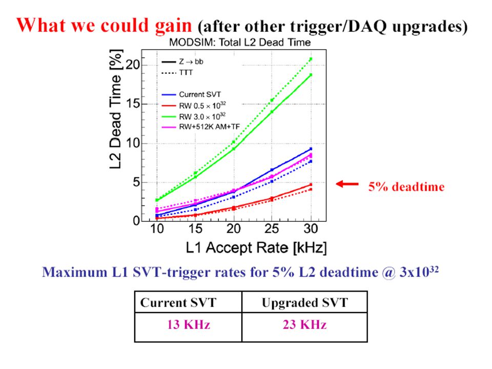
# Lambs (16 Amchips)/ SVTupg/tot keuro wedge SVTnow chips 2 Lamb: 160 kpatt/wedge5384 53 2003 + spare ~500 8 Lamb: 640 kpatt/wedge201536 93 2004 + spare ~2000 Maximum L1 rate for 5% L2 dead time @3x10 32 Current SVT Upgraded SVT 13 KHz 23 KHz Gain of the 2004 SVT upgrade SVT Phyiscs Trigger rates: examples @3x10 32 TriggerL1 Trigger rate Z b-b 26 KHz Hadronic B decay 177 KHz
/ SVTupg/tot keuro wedge SVTnow chips 2 Lamb: 160 kpatt/wedge spare ~500 8 Lamb: 640 kpatt/wedge spare ~2000 Maximum L1 rate for 5% L2 dead 32 Current SVT Upgraded SVT 13 KHz 23 KHz Gain of the 2004 SVT upgrade SVT Phyiscs Trigger rates: 32 TriggerL1 Trigger rate Z b-b 26 KHz Hadronic B decay 177 KHz")
8
Installazione 2005 Eventuale completamento

9
AM LAMB GLUE Input Control RECEIVERs & DRIVERs LAMB CONNECTORs VME INTERFACE HIT/ROAD CONNECTOR TOP GLUE PIPELINE REGISTERs INDI To AMS Clock Distrib. AM++ (9U VME) MAX 2005: 640 Kpatt/wedge
 MAX 2005: 640 Kpatt/wedge.")
10
Year chip boards devel. Total 2003? 120 kE10 kE(test b.) 5 kE 135 kE 2004 - 10 kE (protot.) 30 kE 40 kE 2005 53 kE 100 kE (produc.) 153 k +40 kE +40 kE + 70 kE (produzione) +40 kE tests di qualifica +25 kE package sottile
 5 kE 135 kE kE (protot.) 30 kE 40 kE kE 100 kE (produc.) 153 k +40 kE +40 kE + 70 kE (produzione) +40 kE tests di qualifica +25 kE package sottile.")
11
Upgrade 2004: 600 chips Upgrade 2005: 2000 chips buoni Ipotesi 35/50% yield – fondi 95 + 60 keuros = 155 ke Pilot Run: nuove maschere 210 k$ 1 wf 250 chips contro i 38 MPW PILOT #good costo Mancanticosto RUN chips keuro keuro altrettanti #waferschip 121050/15002156026.4 k$ 252188/31252257055 k$ MPW: buono per piccole produzioni usando maschere del prototipo Si paga solo il silicio ed i 5/6 del wafer si buttano! Con 128 wafers 1700/2430 chips - costo=240 keuro Due strategie di produzione: MPW e Pilot Run

12
Conclusioni Il chip funziona (up to now) Yield ~ 37% Forse si possono usare anche i quasi perfetti: 55-59% Yield puo’ fluttuare molto produzione calcolata su 35% Pilot run: migliore garanzia per avere 2000 chips Si richiedono 70 keuro aggiuntivi per il pilot run
 Yield ~ 37% Forse si possono usare anche i quasi perfetti: 55-59% Yield puo’ fluttuare molto produzione calcolata su 35% Pilot run: migliore garanzia per avere 2000 chips Si richiedono 70 keuro aggiuntivi per il pilot run")
13
SVT Backup slides backup slides

14
Upgrade 2004: 600 chips Upgrade 2005: 2000 chips buoni Ipotesi 35/50% yield – fondi 95 + 60 keuros = 155 ke MPW#goodcostoMancanticosto Wafers chipskeuro keuro/chip 50665/950 1300184/128.5 E 75998/142518530177/124 E 1001330/190019035138/96 E 128170024085138 E PILOT #good costo Mancanti costo RUN chips keuro keuro /chip 121050/150021560 198/139–32/22 E 252188/312522570 101/71 –21/15 E

15
Tsukuba Chicago

16
Tempi di processamento: come agisce l’upgrade ? Ricetta per velocizzare il tempo di esecuzione di SVT: 1.pattern piu’ sottili (AM grande) meno fits. 2.Road Warrior per rimuovere i ghosts Hit Finders Merger Associative Memory Hit Buffer Track Fitter to Level 2 COT tracks fromXTRP 12 fibers hits roads hits x 12 phi sectors Sequencer raw data from SVX front end NUOVA AM piu’ grande Road Warrior SVT exec time ~ proporzionale # candidati da fittare
 meno fits. 2.Road Warrior per rimuovere i ghosts Hit Finders Merger Associative Memory Hit Buffer Track Fitter to Level 2 COT tracks fromXTRP 12 fibers hits roads hits x 12 phi sectors Sequencer raw data from SVX front end NUOVA AM piu’ grande Road Warrior SVT exec time ~ proporzionale # candidati da fittare.")
17
TEMPI DI REALIZZAZIONE Nuova AM-board: inizio estate 2004 ( Pisa ) durante estate 2004: test con FPGA ( Pisa ) Progetto prototipo AM-chip: luglio 2004 ( Ferrara-Pisa ) consegna chip ~2 mesi – disponibile ad ottobre. Nuova LAMB: montare nuovo AM-chip a ottobre 2004 (Pisa) test del chip + scheda: ottobre – dicembre 2004 ( Pisa-Ferrara ) produzione: inizio 2005 ( Pisa-Ferrara ) installazione: estate 2005 ( Pisa-Ferrara ) Altri DAQ/Trigger upgrade: previsti nel 2006 Road Warrior :... (~60 k$ Fermilab) messa in opera entro fine 2003 F. Spinella (in funzione)
 test del chip + scheda: ottobre – dicembre 2004 ( Pisa-Ferrara ) produzione: inizio 2005 ( Pisa-Ferrara ) installazione: estate 2005 ( Pisa-Ferrara ) Altri DAQ/Trigger upgrade: previsti nel 2006 Road Warrior :... (~60 k$ Fermilab) messa in opera entro fine 2003 F. Spinella (in funzione).")
18
RW+TF: F>50 s = 21%

20
Mezzanine slots AUX card Pulsar Custom Mezzanine Bottom view Works up to 100MHz Top view Pulsar (Pulser And Recorder) Design Three ALTERA APEX 20K400 FPGAs I/O Mezzanine cards for: l S-LINK (CERN/LHC) l Hotlink l TAXI l to be specified Self-testable Modular, lego-style open design Replacing > 10 CDF board types all CDF, many ATLAS connectors/standards
 Design Three ALTERA APEX 20K400 FPGAs I/O Mezzanine cards for: l S-LINK (CERN/LHC) l Hotlink l TAXI l to be specified Self-testable Modular, lego-style open design Replacing > 10 CDF board types all CDF, many ATLAS connectors/standards")
21
AMchip L. Zanello

22
Trigger/DAQ Upgrades for Run IIb Need to Maintain or increase bandwidth – Luminosity Rate (= L) – Luminosity inter/x-ing Complexity (and fakes) Event Size, Exec. time –All physics to tape L1 Bandwidth (output to L2) –XFT Purity trigger (L1, L2) –SVT, L2 L2 Exec. t L1 Bandwidth L2 Bandwidth (output to L3) –COT TDC Readout rate –Level 3 Processing L3 Exec. t –Event Builder Readout rate L3 Bandwidth (output to tape) –CSL Tape rate (not under IIb project)
 –XFT Purity trigger (L1, L2) –SVT, L2 L2 Exec. t L1 Bandwidth L2 Bandwidth (output to L3) –COT TDC Readout rate –Level 3 Processing L3 Exec. t –Event Builder Readout rate L3 Bandwidth (output to tape) –CSL Tape rate (not under IIb project).")
Presentazioni simili


; HLT + DAQ; _________________________ NB :non include.>")


 Atlas/FTK M. Villa 04/11/2010.>")


 : 6.23*10 19 p.o.t. - DAQ >99%, 21387 eventi on-time in 2009 (≈ 5500 in.>")

 has now been in stable beams for >12 hours. Delivered.>")