Scaricare la presentazione
La presentazione è in caricamento. Aspetta per favore

1
UA9 stato e richieste future Gianluca Cavoto INFN Roma Riunione CNS1 Bologna, 19 set 2013

2
Outline UA9 results reminder – SPS and H8 data Towards an LHC test – 2013 activity – Location, requirements – Crystals, goniometer – Beam monitoring (Cherenkov) and beam loss monitor (diamond) New crystals for future applications Sblocco s.j. 2013 e richiesta 2013 Outlook 2/27

3
Results SPS: collimation with crystal SPS: crystal radiation resistance H8: new “mirror” crystal SPS (future) operation: beam scraping 3/27
 operation: beam scraping 3/27")
4
4/27 Reduction factor (L am / L ch ) SPS Beam loss maps Beam loss monitor rates along the accelerator ( “ loss maps ” ) are the natural validation for collimation systems. Loss map measurement is not trivial in UA9 – the SPS BLM system is optimized for high-intensity operation in pulsed mode.Lossap measurement in 2011: 2011 data protons Loss map measurement in 2012:maximum possible intensity: 3.3 x 10 13 protons(4 x 72 bunches with 25 ns spacing), average loss reduction in the entire ring ! UA9 installation Sextant 6 2012 data (proton 270 GeV)
, average loss reduction in the entire ring . UA9 installation Sextant data (proton 270 GeV).")
5
5/27 Crystal resistance to irradiation HRMT16-UA9CRY (HiRadMat facility, November 2012): 440 GeV protons, up to 288 bunches in 7.2 μs, 1.1 x 10 11 protons per bunch (3 x 10 13 protons in total) ➔ comparable to asynchronous beam dump in LHC ✓ no damage to the crystal after accurate visual inspection more tests planned to assess possible crystal lattice damage (X-tomography at Grenoble) ✓ accurate FLUKA simulation of energy deposition and residual dose
: 440 GeV protons, up to 288 bunches in 7.2 μs, 1.1 x protons per bunch (3 x protons in total) ➔ comparable to asynchronous beam dump in LHC ✓ no damage to the crystal after accurate visual inspection more tests planned to assess possible crystal lattice damage (X-tomography at Grenoble) ✓ accurate FLUKA simulation of energy deposition and residual dose")
6
Mirror per protoni di 400 GeV/c Cristallo non piegato, spessore circa λ/2 Channeling tra piani (110) Angolo di ingresso circa ½ angolo critico (5 μrad) Deflessione di particelle ad un angolo pari a due volte l’angolo di ingresso (effetto mirror) Traiettorie nel cristallo E. Tsyganov, A. Taratin, NIMA 363, (1995) 511-519 6/27 λ/2
 /27 λ/2.")
7
Cristallo «mirror» 4 mm Membrana di silicio ultrasottile Spessore: 28±1µm Area attiva 4x4 mm 2 Frame spesso (0.5 mm) per evitare deformazioni del cristallo 400GeV/c protons θ c ~ 10.6 µrad λ ch ~ 56 µm Realizzato a INFN FE 7/27
 per evitare deformazioni del cristallo 400GeV/c protons θ c ~ 10.6 µrad λ ch ~ 56 µm Realizzato a INFN FE 7/27")
8
Mirror per protoni di 400 GeV/c Horizontal deflection angle [µrad] Horizontal incoming angle *[µrad] Simulazione E. Bagli, V. Guidi NIMB 309 124 Dimostrata la possibilità di manipolare le traiettorie di fasci di particelle anche tramite cristalli non curvi. Spessore cristallo inferiore ad una oscillazione di channeling Risultato sperimentale ad H8 8
![Mirror per protoni di 400 GeV/c Horizontal deflection angle [µrad] Horizontal incoming angle *[µrad] Simulazione E.](http://images.slideplayer.it/35/10291520/slides/slide_8.jpg "Bagli, V. Guidi NIMB Dimostrata la possibilità di manipolare le traiettorie di fasci di particelle anche tramite cristalli non curvi. Spessore cristallo inferiore ad una oscillazione di channeling Risultato sperimentale ad H8 8.")
9
Beam scraping in the SPS: – reduce beam tails before injection in the LHC (reduce losses at injections) – current system relies on the fast movement of a graphite foil across the beam periphery – possible upgrade with a local orbit bump that deflects the beam towards a fixed scraper. 9/27 Beam scraping with a multi-strip crystal in multi-VR Presented by O. Mete, 15 January 2013 crystal scraper Possible crystal-based beam scraper system with a magnetic bump. absorber First application of crystal in accelerator operations possible Test foreseen after LS1 Richiesta Set 2013: multistrip crystal

10
Attivita’ 2013 Simulations for LHC – Choice of LHC UA9 location Devices for LHC – Titanium holder for LHC crystals – Low miscut crystals – Piezo-goniometer – In-vacuum beam monitoring (Cheronkov) – Fast beam loss monitor (diamond) 10/27
 – Fast beam loss monitor (diamond) 10/27")
11
LHC crystal position choice 11//27 – Finding a match between the primary collimator (crystal) and the secondary collimator (absorber) – Between crystal and absorber a location for beam monitor (Cherenkov) – Detailed loss map (simulated) available INFN NA
 and the secondary collimator (absorber) – Between crystal and absorber a location for beam monitor (Cherenkov) – Detailed loss map (simulated) available INFN NA")
12
Vertical Crystal and Vertical Absorber Horizontal Crystal and Horizontal Absorbers Two collimation systems one vertical, one horizontal Green light from CERN collimation group in Apr 2013 Produce devices now and install them (goniometers) in 2014 12/27
 in /27")
13
Crystal open issues Crystal and holder weigh ≤ 300 g (new constraint for LHC) Holder with low emissivity to mitigate the e-cloud process Sputter the holder with carbon composite, heat holder to 300deg 13/27 STF49 (strip) length: 0.8 mm bending angle: 246 μrad bent planes: torsion < 10 μrad / mm amorphous layer < 100 μm mis-cut angle < 170 μrad Use titanium grade 5 for crystal holder holder crystal Currently under construction Miscut problem: External surface parallel to lattice plane within critical angle (2 microrad)
 Holder with low emissivity to mitigate the e-cloud process Sputter the holder with carbon composite, heat holder to 300deg 13/27 STF49 (strip) length: 0.8 mm bending angle: 246 μrad bent planes: torsion < 10 μrad / mm amorphous layer < 100 μm mis-cut angle < 170 μrad Use titanium grade 5 for crystal holder holder crystal Currently under construction Miscut problem: External surface parallel to lattice plane within critical angle (2 microrad)")
14
Miscut: Lucidatura magnetoreologica (MRF) Wafer, superficie iniziale PV 2.18 um RMS 0.39 um Superficie dopo prima lucidatura PV 0.615 um RMS 0.14 um Superficie finale PV 0.177 um RMS 0.01 um Caratterizzazione XRD e RBS-channeling mostrano che la qualità cristallina non viene degradata dal processo di lucidatura La MRF è la tecnica ideale per la diminuzione del miscut di wafers di silicio 14/27 INFN FE
 Wafer, superficie iniziale PV 2.18 um RMS 0.39 um Superficie dopo prima lucidatura PV um RMS 0.14 um Superficie finale PV um RMS 0.01 um Caratterizzazione XRD e RBS-channeling mostrano che la qualità cristallina non viene degradata dal processo di lucidatura La MRF è la tecnica ideale per la diminuzione del miscut di wafers di silicio 14/27 INFN FE")
15
LHC goniometer 15/27

16
A piezo-goniometer 16 /27

17
Cherenkov beam monitoring Geant 4 simulation good to assess the feasibility. Each optical interface need a specific hardware test 17/27 INFN RM

18
Test at BTF: silica radiator (and fibers) Diamond 1mm x 1mm 18/27 Radiator + PMT Radiator + fibers + PMT MA-PMT Silica radiator Fibers bundle -Optical readout by MA-PMT R5900U-L16 (quartz plate window) -10.1mm x 20.1mm x 105mm quartz radiator Either directly coupled with the 4 central MA channels OR via a bundle of silica fibers
 Diamond 1mm x 1mm 18/27 Radiator + PMT Radiator + fibers + PMT MA-PMT Silica radiator Fibers bundle -Optical readout by MA-PMT R5900U-L16 (quartz plate window) -10.1mm x 20.1mm x 105mm quartz radiator Either directly coupled with the 4 central MA channels OR via a bundle of silica fibers")
19
Setup 2: Measurements -Larger relative increase of light @45° (300-400%) than in MA-PMT direct coupled, this due to optic acceptance angle of fibers (numerical aperture) -Optical coupling quality efficiency ~10% 19/27 HV MAPMT: -700V Particles (e-)
 than in MA-PMT direct coupled, this due to optic acceptance angle of fibers (numerical aperture) -Optical coupling quality efficiency ~10% 19/27 HV MAPMT: -700V Particles (e-)")
20
Diamonds for UA9 fast losses SPS installation Diamond and amplifiers 20 dB 40 dB Diamond case AmplifiersDiamond board HV (100 or 500 V) 20/27 INFN LNF
 20/27 INFN LNF")
21
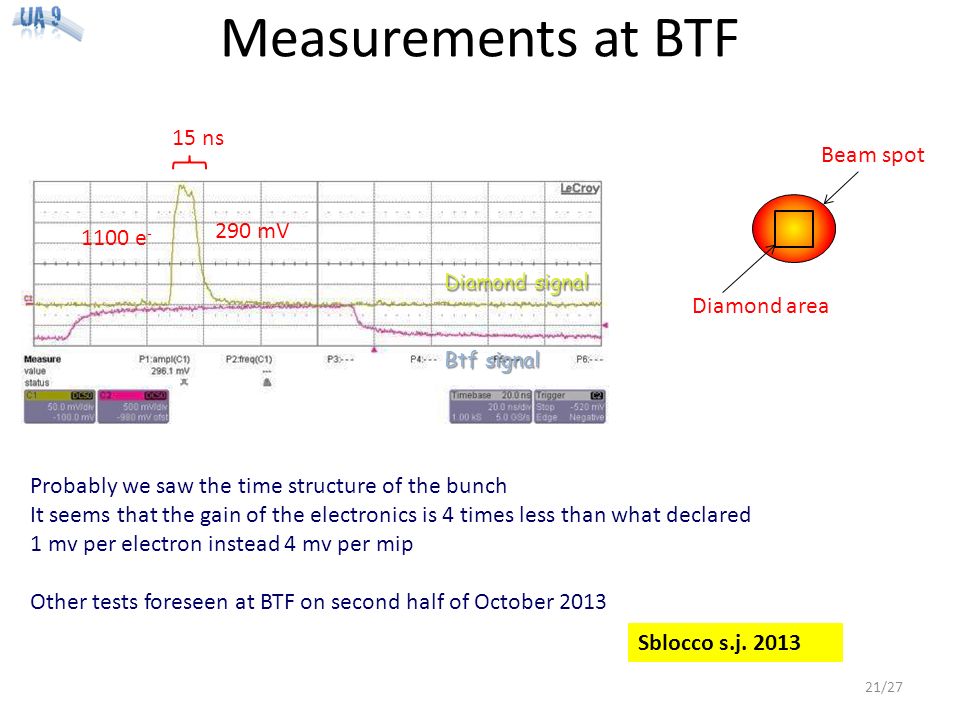
Measurements at BTF 15 ns 290 mV 1100 e - Probably we saw the time structure of the bunch It seems that the gain of the electronics is 4 times less than what declared 1 mv per electron instead 4 mv per mip Other tests foreseen at BTF on second half of October 2013 Diamond area Beam spot Diamond signal Btf signal 21/27 Sblocco s.j. 2013
22
Attivita’ future 22/27 2014: completare installazione e validazione di strumentazione Goniometri Beam monitor (Cherenkov + diamonds) Sviluppo di cristalli speciali Fine 2014: Test ad H8
 Sviluppo di cristalli speciali Fine 2014: Test ad H8")
23
Dove mettiamo il cristallo su LHC TCSM.D5R7.B1 @ 20104m equipaggiata col supporto per collimatore, analoga alla posizione TCSM.D4L7.B1 per il goniometro orizzontale Engineering Change request for installation in LHC 23/27

24
Scheme of the diamond system HV and Preamp Diamond Rad Hard Electronics 10 m 16 channel mother board FPGA Ethernet 16 ch SPS period Possibility to fold the counting rate bunch per bunch BEAM PIPE 24/27 modify a system already developed in Frascati for Mu2e (APD)
")
25
Un channeling super-efficiente z1z1 z2z2 z 1 ~λ/12 - λ/8 z 1 -z 2 ~λ/8 - λ/6 λ: lunghezza d’onda delle oscillazioni di channeling In un cristallo «classico» i protoni che, pur trovandosi in regime di channeling incidono «vicino» ai piani atomici vengono dechannelati quasi subito per dechanneling nucleare. I protoni più distanti attraversano tutto il cristallo e vengono deflessi Massima efficienza di channeling raggiungibile ~ 83% (già raggiunta sperimentalmente, W. Scandale et al., Physics Letters B 680 (2009) 129–132). Una lente cristallina posta prima di un «cristallo classico» permette di «recuperare» la frazione di protoni che inciderebbe vicino ai piani atomici aumentando il loro parametro d’impatto. Efficienza di channeling prevista ~ 99% 25/27 V. V. Tikhomirov JINST 2 P08006 (2007)
 129–132). Una lente cristallina posta prima di un «cristallo classico» permette di «recuperare» la frazione di protoni che inciderebbe vicino ai piani atomici aumentando il loro parametro d’impatto. Efficienza di channeling prevista ~ 99% 25/27 V. V. Tikhomirov JINST 2 P08006 (2007).")
26
Holder «dinamico» Parametri che influenzano efficienza di channeling: raggio e spessore cristallo. Nei sistemi attuali montati in SPS queste quantità sono «fisse». Variare almeno uno di questi parametri potrebbe dare importanti informazioni circa i parametri ottimali per la collimazione di SPS/LHC, ma questo richiede di sostituire il cristallo!! 26/27

27
Sommario Costruzione e installazione di dispositivi per LHC – Procede e terminera’ nel 2014 » Primi test nel 2015 – Cristalli sono una seria opzione per collimazione in LHC HI-LUMI – Fascio estratto a LHC: “AFTER”? UA9 su SPS e H8: test facility consolidate – per nuovi cristalli » super-channeling, multistrip, lenti cristalline… – per studiare interazione cristalli-acceleratore. – per studiare interazioni coerenti nei cristalli » ioni e cristalli, PXR, interazione inelastiche e channeling…) 27/27 UA9: tecnologia di frontiera (cristalli, goniometri, beam monitoring) in cui l’INFN ha un innegabile primato.
 27/27 UA9: tecnologia di frontiera (cristalli, goniometri, beam monitoring) in cui l’INFN ha un innegabile primato..")
28
Backup slides 28

29
29 Crystal collimation Bent crystals as primary collimators: – coherent interaction (channeling) of particles impinging on the crystal: ✓ reduce probability of diffractive events and ion fragmentation and dissociation ✓ reduce loss rate close to the crystal localization of the losses on a single absorber, at larger distance from the beam (thanks to large deflection angle) small angular acceptance (2 × θ c ) MCS ~ 3.6 μrad (7 TeV) Amorphous (1 m CFC) Crystal (Channeling) (3 mm Si) optimal ~ 40 μrad (7 TeV) ch ~ α bend R.W. Assmann, S. Redaelli, W. Scandale, “ Optics studies for a possible crystal-based collimation system for the LHC ”, EPAC 2006

30
QMP32 (quasi-mosaic) length: 1 mm bending angle: 175 μrad bent planes: amorphous layer < 100 μm mis-cut angle < 50 μrad STF49 (strip) length: 0.8 mm bending angle: 246 μrad bent planes: torsion < 10 μrad / mm amorphous layer < 100 μm mis-cut angle < 170 μrad Crystals: open issues Crystal and holder weigh ≤ 300 g (new constraint for LHC) Use Titanium grade 5 holders Holder with low emissivity to mitigate the e-cloud process Sputter the holder with carbon composite Crystal defects to be compensated (for SPS and LHC) Miscut angle ≤ critical angle -> new cutting procedure assisted by interferometry Torsion not exceeding 1 μrad/mm -> adjustment of the crystal holder either with an interferometer or in a test in the north area of the SPS Size of the amorphous layer at the crystal surface ≤ 1 μ m -> optical and chemical treatment of the crystal surface Effect of the miscut Compensation of the miscut angle is the most demanding request not yet implemented 30
 length: 1 mm bending angle: 175 μrad bent planes: amorphous layer < 100 μm mis-cut angle < 50 μrad STF49 (strip) length: 0.8 mm bending angle: 246 μrad bent planes: torsion < 10 μrad / mm amorphous layer < 100 μm mis-cut angle < 170 μrad Crystals: open issues Crystal and holder weigh ≤ 300 g (new constraint for LHC) Use Titanium grade 5 holders Holder with low emissivity to mitigate the e-cloud process Sputter the holder with carbon composite Crystal defects to be compensated (for SPS and LHC) Miscut angle ≤ critical angle -> new cutting procedure assisted by interferometry Torsion not exceeding 1 μrad/mm -> adjustment of the crystal holder either with an interferometer or in a test in the north area of the SPS Size of the amorphous layer at the crystal surface ≤ 1 μ m -> optical and chemical treatment of the crystal surface Effect of the miscut Compensation of the miscut angle is the most demanding request not yet implemented 30")
31
31 M Pesaresi et al 2011 JINST 6 P04006 Test beam facility in SPS North Area Semi-permanent installation: – tracking detectors – 4-axis goniometer – GEM and Medipix detectors for imaging Crystal tested with a primary beam (400 GeV/c/n protons or Pb ions): – crystal optimized for SPS or LHC (constant technological improvements) –“ exotic ” crystals (multi-crystals, crystals with variable curvature,...) – new physics (radiation production, interaction rates, ultra-thin crystals,...) Data-taking in stand-by in 2014 On-going activity FLUKA model of the line, the detector and the crystal What for? Past data re-interpretation Neutron detector for the ion fragmentation Pion detector for the proton nuclear events Instrumented secondary absorber

32
32 2012 data protons (270 GeV) Reduction factor (L am / L ch ) Beam loss maps Beam loss monitor rates along the accelerator ( “ loss maps ” ) are the natural validation for collimation systems. Loss map measurement is not trivial in UA9: – the SPS BLM system is optimized for high-intensity operation in pulsed mode, – UA9 operates at low intensity and low loss rate (loss signal below the BLM threshold). Loss map measurement in 2011: 2011 data protons Loss map measurement in 2011:intensity increased from 1 bunch (I = 1.15 x 10 11 p) to 48 bunches, clear reduction of the losses seen in Sextant 6. Loss map measurement in 2012:maximum possible intensity: 3.3 x 10 13 protons (4 x 72 bunches with 25 ns spacing), average loss reduction in the entire ring! UA9 installation Sextant 6 2012 results
. Loss map measurement in 2011: 2011 data protons Loss map measurement in 2011:intensity increased from 1 bunch (I = 1.15 x p) to 48 bunches, clear reduction of the losses seen in Sextant 6. Loss map measurement in 2012:maximum possible intensity: 3.3 x protons (4 x 72 bunches with 25 ns spacing), average loss reduction in the entire ring. UA9 installation Sextant results.")
33
33 Beam scraping with a multi-strip crystal in multi-VR Presented by O. Mete, 15 January 2012 crystal scraper Possible crystal-based beam scraper system with a magnetic bump. absorber Beam scraping in the SPS: – reduce beam tails before injection in the LHC (reduce losses at injections) – current system relies on the fast movement of a graphite foil across the beam periphery – possible upgrade with a local orbit bump that deflects the beam towards a fixed scraper. A crystal could be used to localize all the losses in the absorber: – particles intercepted by the crystal are extracted (by volume reflection) rather than absorbed: absorber not subjected to multi-turn passage of particles (heating reduced) impact parameter on the absorber defined by crystal deflection angle (i.e. possibly one or more mm) – reduced probability of diffractive events (and fragmentation and dissociation, if used with ions). tests performed in November 2012 (at low energy) results presented in January 2013: investigation will continue after the CERN long shutdown 2012 results
 – current system relies on the fast movement of a graphite foil across the beam periphery – possible upgrade with a local orbit bump that deflects the beam towards a fixed scraper. A crystal could be used to localize all the losses in the absorber: – particles intercepted by the crystal are extracted (by volume reflection) rather than absorbed: absorber not subjected to multi-turn passage of particles (heating reduced) impact parameter on the absorber defined by crystal deflection angle (i.e. possibly one or more mm) – reduced probability of diffractive events (and fragmentation and dissociation, if used with ions). tests performed in November 2012 (at low energy) results presented in January 2013: investigation will continue after the CERN long shutdown 2012 results.")
34
34 Crystal installation in LHC recommended by the LHCC. Roadmap for the experiment in LHC: – propose and install a minimal number of devices in the LHC (possibly during the shutdown in 2013-2015) – demonstrate the extraction of the beam halo in the LHC with low intensity – assess the theoretical improvements with respect to standard collimation Possible experimental layout under investigation: – only one beam (beam 1), two crystals (horizontal & vertical) close to the primary collimators highest radiation area, tight space allowance – extracted beam absorbed by secondary collimators simulation work ongoing to assess the optimal collimation system setup during the tests – Cherenkov detector (in vacuum) in front of the absorber Towards an installation in the LHC 34 horizontal & vertical crystals crystal channeled beam absorber beam envelope
 – demonstrate the extraction of the beam halo in the LHC with low intensity – assess the theoretical improvements with respect to standard collimation Possible experimental layout under investigation: – only one beam (beam 1), two crystals (horizontal & vertical) close to the primary collimators highest radiation area, tight space allowance – extracted beam absorbed by secondary collimators simulation work ongoing to assess the optimal collimation system setup during the tests – Cherenkov detector (in vacuum) in front of the absorber Towards an installation in the LHC 34 horizontal & vertical crystals crystal channeled beam absorber beam envelope.")
35
SixTrack simulation for crystal With Crystal D.Mirarchi 35

36
Fabbricazione di cristalli a basso miscut Per incrementare l’efficienza di collimazione, l’esperimento UA9 richiede la fabbricazione di cristalli con miscut (angolo tra la superficie fisica del cristallo ed i piani atomici) inferiore a 10 µrad. I cristalli sono ottenuti da wafers di silicio usati in microelettronica, settore nel quale questo parametro non è di rilevante importanza Si è resa necessaria una lavorazione preliminare delle superfici dei wafers per ridurne il miscut 36

37
Lucidatura magnetoreologica Acquistati wafers Effettuata misura del miscut di 50 wafers e selezionati i 5 migliori: Planarizzazione e riduzione miscut ottobre (legata alla disponibilità della ditta esterna) Miscut (urad) 24 ± 0.5 30 ± 0.5 33 ± 0.5 45 ± 0.5 54 ± 0.5 37
 Miscut (urad) 24 ± ± ± ± ±")
38
Autocollimatore auto-costruito Progettazione, fabbricazione e caratterizzazione di un autocollimatore (e relativo software di controllo e analisi dati) 38
 38")
39
Autocollimatore auto-costruito Accuratezza e precisione: 0.5 μrad Range di misura: 0.6 gradi (x e y) Costo di realizzazione circa 8.000 euro Costo di strumenti analoghi sul mercato: circa 43.000 euro. Alimentazione tramite porta USB di un pc. Sorgente LED Pin-hole Beam splitter Lente collimatrice Telecamera 39

40
LHC tunnel transverse section Moving detector (PMT) to a far (on the wall opposite to beam pipe: ~5m away) and “cooler” [~100 kRad/year, TBC] Readout electronics can be hundred meters away FLUKA simulation on-going to estimate dose. Beam pipes PMT Location ✭ 40
![LHC tunnel transverse section Moving detector (PMT) to a far (on the wall opposite to beam pipe: ~5m away) and cooler [~100 kRad/year, TBC] Readout electronics can be hundred meters away FLUKA simulation on-going to estimate dose.](http://images.slideplayer.it/35/10291520/slides/slide_40.jpg "Beam pipes PMT Location ✭ 40.")
41
Rad-hard optical fibers ALL SILICA AS600/660UVST tr Core 600μm ± 2% Cladding 660mm ± 2% ACRYLATE Coating 770μm ± 3% Buffer 920μm ± 5% Attenuation @350nm <=0,06dB/m Operational in 200-1200 nm range 18 rad/s (0.3 rad/s LHC worst) NB: Silica quartz fiber have good attenuation in blu-UV but expensive (15 eur/m!) 41
 NB: Silica quartz fiber have good attenuation in blu-UV but expensive (15 eur/m!) 41")
42
Test Setup @BTF (July) Ethernet BTF Calo (Pb Glass Cerenkov) Control Room PC -Test of Čerenkov Radiator was done on 8-13 July 2013 @ BTF - fine-adjustable-multiplicity 500MeV electron’s beam -BTF Čerenkov Calorimeter downstream to measure rate and multiplicity of particle -Signals were acquired by two 4 channels Lecroy Oscilloscope (WaveRunner 625zi and WaveRunner 6050) Oscilloscope Čerenkov Radiator Beam window Hand Platform Rotation Stage (Newport M-RS 40) FAN-IN/OUT Summed Signal MA PMT Signals BTF Calorimeter Beam Finger scint. Cerenkov BTF remotely controlled table ~50 cm ~105 cm 42

43
Setup 2 -Optical readout by MA-PMT R5900U-L16 (quartz plate window) -10.1mm x 20.1mm x 105mm quartz radiator coupled with MA-PMT through 25 quartz fibers 120mm long 43
 -10.1mm x 20.1mm x 105mm quartz radiator coupled with MA-PMT through 25 quartz fibers 120mm long 43")
44
Fibers cable 10 mm 20 mm Fibers: Fibertech Type AS600/660 UVST Coating 780 μm Silicone Jacket 940 μm Tefzel 0.6 dB/m at 350 nm Remaining efficiency losses due to fiber’s lapping/optical coupling -Fibers was hand-cut by means of diamond wheel, then it was hand-lapped by glass sand papers with increasingly grit ( from 400 to 1200 by steps of 200) -Lower light collection efficiency due to geometry -Fibers area: 25*π*(0.6mm/2) 2 =7.07mm 2 -Quartz Radiator Area:20mm*10mm=200mm 2 -Geometrical losses factor: 7.07/200= ~ 3.5% 44
 -Lower light collection efficiency due to geometry -Fibers area: 25*π*(0.6mm/2) 2 =7.07mm 2 -Quartz Radiator Area:20mm*10mm=200mm 2 -Geometrical losses factor: 7.07/200= ~ 3.5% 44")
45
LNF BTF fiber tests (Nov 2012) LEONI FiberTech ALL SILICA AS 400/440 UVPI external diameter : 0.465 mm core diameter : 0.400 mm Cladding Diameter : 0.440 mm Cladding doping: Flourine Coating Material : polyamide NA = 0.22 attenuation: 0.008dB/m 4 silica fibers readout with SiPM Manual Goniometer to orient Fibers External calorimeter to measure flux 45
 LEONI FiberTech ALL SILICA AS 400/440 UVPI external diameter : mm core diameter : mm Cladding Diameter : mm Cladding doping: Flourine Coating Material : polyamide NA = 0.22 attenuation: 0.008dB/m 4 silica fibers readout with SiPM Manual Goniometer to orient Fibers External calorimeter to measure flux 45")
46
Dose in LHC at (possible) detector location This was a first Max Dose (close to pipe) 100 kGy/year 10 14 neutron/cm 2 /year (thermal neutron) A.Lechner (FLUKA team) This was a worst case scenario: we now choose a less radioactive zone 46
 detector location This was a first Max Dose (close to pipe) 100 kGy/year neutron/cm 2 /year (thermal neutron) A.Lechner (FLUKA team) This was a worst case scenario: we now choose a less radioactive zone 46")
47
Readout scheme COAXIAL cable Metal dynode or Multi-ChannelPlate [expensive but <100 ps resolution! ] 20% QE in blu-UV region Require quartz window (to be transparent to blue) Photodetector: PMT Vacuum transition Need radiation hard fibers Fibers bundle 5-10 m 47
 Photodetector: PMT Vacuum transition Need radiation hard fibers Fibers bundle 5-10 m 47.")
48
Hamamatsu radiation test on PMT From Hamamatsu’s PMT handbook. Glass Window must be absolutely avoided instead. 48

49
Geant4 simulation 49

50
On board calibration tool – LED light Measures the stability of the gain Inject light into the bar – use one special optical fiber – Does not depend on the stability of the LED!!! – Inject light at two point of the bar Measure attenuation length variation of the bar 50

51
Cherenkov light in fibers! – Cherenkov light in 0.5 mm quartz fiber: » 0.3 pe/0.3mm/mip with SiPM (40% QE) -> 10 pe/mip » In agreement with G4 simulation! – 100 particles channeled/bunch -> percent level measurement! 46 deg should be optimal to collect “direct” light Overall difference due to SiPM – fiber optical coupling Relative angle particle-fiber axis 51
 -> 10 pe/mip » In agreement with G4 simulation. – 100 particles channeled/bunch -> percent level measurement. 46 deg should be optimal to collect direct light Overall difference due to SiPM – fiber optical coupling Relative angle particle-fiber axis 51.")
52
Un channeling super-efficiente La fabbricazione di un cristallo dotato di lente cristallina è possibile tramite tecniche di microlavorazione del silicio. 52

53
Progettazione holder in titanio Richiesta della collaborazione UA9 di fabbricare un holder in titanio Test evidenziano che titanio «grado 5» è compatibile con l’ambiente di LHC Simulazioni FEM per ottimizzare la geometria dell’holder. 53

54
Holder «dinamico» Holder in titanio con possibilità di regolare in modo dinamico la piegatura del cristallo tramite un attuatore Attuatore lineare 54

55
Diamonds and electronics Is a De Beers company that sell the sensors The poly-crystalline should be good for us as we need a counting device (1 cm 2 ) The mono-crystalline is typically used for spectroscopy and fusion diagnostics The contacts could be made by Cividec … or by Emanuele Pace at Firenze (?) For the electronic readout and HV PS, our idea is to modify a system already developed in Frascati for Mu2e (APD) G. Corradi Mother board and FEE cards with amplifier and HV (500V) 55
 55.")
56
56 Crystal resistance to irradiation IHEP U-70 (Biryukov et al, NIMB 234, 23-30): ➡ 70 GeV protons, 50 ms spills of 10 14 protons every 9.6 s, several minutes irradiation ✓ channeling efficiency unchanged. SPS North Area - NA48 (Biino et al, CERN-SL-96-30-EA): ➡ 450 GeV protons, 2.4 s spill of 5 x 10 12 protons every 14.4 s, one year irradiation, 2.4 x 10 20 protons/cm 2 in total, ✓ channeling efficiency reduced by 30%. HRMT16-UA9CRY (HiRadMat facility, November 2012): ➡ 440 GeV protons, up to 288 bunches in 7.2 μs, 1.1 x 10 11 protons per bunch (3 x 10 13 protons in total) ➔ comparable to asynchronous beam dump in LHC ✓ no damage to the crystal after accurate visual inspection more tests planned to assess possible crystal lattice damage – accurate FLUKA simulation of energy deposition and residual dose 56
: ➡ 450 GeV protons, 2.4 s spill of 5 x protons every 14.4 s, one year irradiation, 2.4 x protons/cm 2 in total, ✓ channeling efficiency reduced by 30%. HRMT16-UA9CRY (HiRadMat facility, November 2012): ➡ 440 GeV protons, up to 288 bunches in 7.2 μs, 1.1 x protons per bunch (3 x protons in total) ➔ comparable to asynchronous beam dump in LHC ✓ no damage to the crystal after accurate visual inspection more tests planned to assess possible crystal lattice damage – accurate FLUKA simulation of energy deposition and residual dose 56.")
57
Concept for in-vacuum detector Use a well polished quartz Cherenkov radiator to intercept channeled beam – 1 cm thick Quartz bar in vacuum – Need to design vacuum-air interface to bring light outside Attach silica fibers (in air) to the quartz bar – Bring light far away from beam pipe (few m) to a PMT – Bring PMT signal very far (hundred m) to electronics Motorization and beam pipe insert similar to goniometer – Retractable finger 57
 to the quartz bar – Bring light far away from beam pipe (few m) to a PMT – Bring PMT signal very far (hundred m) to electronics Motorization and beam pipe insert similar to goniometer – Retractable finger 57")
Presentazioni simili


 0.8 mm pitch M = 2, FoV = 25×25 mm 2 50×50 mm 2 LaBr 3 (Ce) 4 mm thick, 3 mm thick window M = 2, FoV = 25×25 mm 2 50×50 mm 2 CsI(Na)>")


>")

 Profili.>")

