Scaricare la presentazione
La presentazione è in caricamento. Aspetta per favore

1
Architettura Energy (sviluppo del nodo) 2013-07-17
")
2
Architettura Energy – Componenti base TMDSSOLARCEXPKIT Concerto-based Solar Explorer Development TMDSHVMPPTKIT High Voltage Isolated Solar MPPT Developers Kit TMDSHV1PHINVKIT High Voltage Single Phase Inverter Development Kit + TMDSHVMPPTKIT TMDSHV1PHINVKIT Rebuild Code modification Stand alone test Rebuild Code modification Stand alone test Rebuild Code modification Stand alone test Objective - good understanding of the SW and HW architecture in order to use the modules as the elementary components of the system architecture (HW & SW modificaiton needed!) Rebuild Code modification Stand alone test
 Rebuild Code modification Stand alone test")
3
P V V sense I sense 60V DC 220V AC 0-60V DC 0-48V DC 220V DC 220V AC I sense II V V

4
Da BOOST a SEPIC (1) (1) single ended primary inductor converter TMDSHVMPPTKIT (BOOST converter) TMDSHVMPPTKIT modificato (SEPIC converter)
 (1) single ended primary inductor converter TMDSHVMPPTKIT (BOOST converter) TMDSHVMPPTKIT modificato (SEPIC converter)")
5
Da BOOST a SEPIC (1)
")
6
I sense 0-48V DC P V sense 0-60V DC 1. I sense Introdurre sense di corrente ($!) Modificare FW (controllo + comunicazione) Collegare il carico (batteria) Caratterizzare la batteria Introdurre sense di corrente ($!) Modificare FW (controllo + comunicazione) Collegare il carico (batteria) Caratterizzare la batteria Modifiche HW apportate al device TMDSHVMPPTKIT (High Voltage Isolated Solar MPPT Developers Kit)
 Modificare FW (controllo + comunicazione) Collegare il carico (batteria) Caratterizzare la batteria Introdurre sense di corrente ($!) Modificare FW (controllo + comunicazione) Collegare il carico (batteria) Caratterizzare la batteria Modifiche HW apportate al device TMDSHVMPPTKIT (High Voltage Isolated Solar MPPT Developers Kit).")
7
in blu la tensione in ingresso in giallo la tensione in uscita Modifiche HW apportate al device TMDSHVMPPTKIT (High Voltage Isolated Solar MPPT Developers Kit)
")
8
DescrizioneSetHWFW SEPIC (1) con set di potenza massimaPmax SEPIC (1) con set di tensione in uscitaVset50% - SEPIC (1) con set di corrente in uscitaIset50% - INVERTER controllato in tensioneVset V Completamento blocchi elementari PVI (1) single ended primary inductor converter situazione all’ultimo meeting
 con set di potenza massimaPmax SEPIC (1) con set di tensione in uscitaVset50% - SEPIC (1) con set di corrente in uscitaIset50% - INVERTER controllato in tensioneVset V Completamento blocchi elementari PVI (1) single ended primary inductor converter situazione all’ultimo meeting")
9
Sense di corrente

10
AD629

11
Sense di corrente AD629 SPECIFICHE NON RISCONTRATE SPERIMENTALMENTE

12
Sense di corrente AD629 “As the high voltage current sense we are using the AD629 and we are experiencing the following problem (both in the simulation and in the real world behavior of the IC): the 100V common mode applied to the input of the device (no load connected after the Rhunt) generates an offset of about 15mV (despite of the 2mV/240V error voltage reported in Figure 3 of the AD629 datasheet). We have also tried to compensate the Rshunt, adding an Rcomp of the same value to the low impedance side of the shunt resistor (Figure 36 of the AD629 datasheet), but nothing changed”. Contattato il supporto tecnico Risposta Circuit Note CN-0240
, but nothing changed . Contattato il supporto tecnico Risposta Circuit Note CN")
13
Sense di corrente INA117 Prestazioni migliorate, ma non sufficienti Prestazioni migliorate, ma non sufficienti

14
Sense di corrente INA168

15
Sense di corrente INA168 Application Report SLLA190 – February 2006 corrente variabile con la tensione di alimentazione

16
Sense di corrente INA168 Application Report Modificata SLLA190 – February 2006 corrente non costante a causa di deriva termica

17
Sense di corrente INA168 Soluzione finale

18
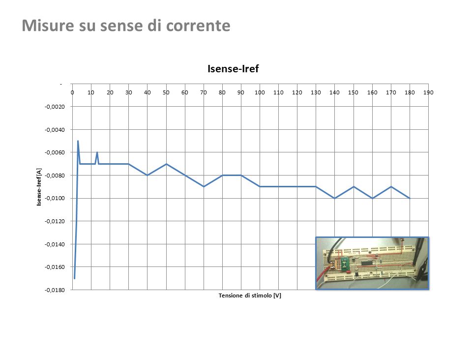
Misure su sense di corrente su INA168

19
Misure su sense di corrente

21
DescrizioneSetHWFW SEPIC (1) con set di potenza massimaPmax SEPIC (1) con set di tensione in uscitaVset - SEPIC (1) con set di corrente in uscitaIset - INVERTER controllato in tensioneVset V Completamento blocchi elementari PVI (1) single ended primary inductor converter situazione attuale
 con set di potenza massimaPmax SEPIC (1) con set di tensione in uscitaVset - SEPIC (1) con set di corrente in uscitaIset - INVERTER controllato in tensioneVset V Completamento blocchi elementari PVI (1) single ended primary inductor converter situazione attuale")
22
Protocollo di comunicazione

23
P V V sense I sense 60V DC 220V AC 0-60V DC 0-48V DC 220V DC 220V AC I sense II VV Current = ± 100% P = 0%…100% ON/OFF A B C D

24
P V 60V DC 0-60V DC 0-48V DC 220V DC 220V AC I V V A B D C Interfaccia comandi layer fisico USB (cfr. tabella comandi) Bus dati locale layer fisico 485
 Bus dati locale layer fisico 485.")
25
ComandoParameters Descrizione set_valuesnode, value, time Imposta i parametri dei singoli rami (A, B, C, D) utilizzati durante il funzionamento in modalità manuale get_status Va, Pa, Vb, Ib, Vc, Ic, Vd, Id, fd, Vbatt, Cbatt Restituisce i valori di tensione, corrente, potenza dei singoli rami (A, B, C, D) in aggiunta ad altri parametri di interesse (da definire) set_profile? Imposta il profilo predefinito per il funzionamento del nodo in modalità automatica set_modeauto/manual/diagnosticImposta la modalità operativa del nodo set_paramsbatt_typeImposta i parametri operativi del nodo Ipotesi preliminare di protocollo di comunicazione

26
Middleware Solver

Presentazioni simili


 Mauro Citterio,Massimo Lazzaroni,Stefano Latorre Workshop Apollo Milano 18/12/2012.>")


 ed altri namespaces La Class Library è organizzata gerarchicamente mediante.>")