Scaricare la presentazione
La presentazione è in caricamento. Aspetta per favore

1
X Series ICP-MS Training Course

2
X Series ICP-MS Training Course

3
Comparison of ICP-MS to Other Techniques
Shares applications with ICP-AES and AA Shares multielement characteristic with ICP-AES Shares analytical speed with ICP-AES Shares detection limits with GFAAS Unique in isotope measurement capability Unique in rapid semiquantitative analysis

4
X Series ICP-MS Training Course
Introduction to ICP-MS theory and X Series ICP-MS PlasmaLab Analytical Method Development Dealing with interferences

5
ICP-MS Application Areas

6
Introduction to ICP-MS Theory and X Series ICP-MS
Li K Rb Cs Fr Be Mg Ca Sr Ba Na Sc Y La Ac Ti Zr Hf V Nb Ta Ra Cr Mo W Mn Tc Re Fe Ru Os Co Rh Ir Ni Pd Pt Cu Ag Au Zn Cd Hg Ga In Tl Ge Sn Pb As Sb Bi Te Po Br I At Kr Xe Rn Se B Al C Si N P S F Cl Ne Ar O Ce Th Pr Pa Nd U Pm Np Sm Pu Eu Am Gd Cm Tb Bk Dy Cf Ho Es Er Fm Tm Md Yb No Lu Lr He Samples take many forms throughout our environment The varying sample types place high demands upon the instrument design

7
ICP-MS Positioning Cost ICPMS ICP-OES FAA GFAA Speed Sensitivity

8
SPETTROSCOPIA ATOMICA
ICP-MS ICP-OES GF-AAS Flame AA 100% 0.1 % ppm ppb ppt ppq Range di misure

9
ICP-MS : Inductively Coupled Plasma - Mass Spectrometry
ICP-MS INTRODUZIONE ICP-MS : Inductively Coupled Plasma - Mass Spectrometry Tecnica multielementale Ampio range di elementi analizzabili (> 75) Detection Limits di ng/L in soluzione Alta produttività (campioni /giorno : 500) Range dinamico di linearità esteso
 Detection Limits di ng/L in soluzione. Alta produttività (campioni /giorno : 500) Range dinamico di linearità esteso.")
10
ICP-MS ASPETTI FONDAMENTALI ICP : Sorgente di ioni
Atomi e Molecole Ioni Mass Spectrometer : Filtro Gli ioni vengono separati in funzione del rapporto m/z Segnale proporzionale al numero di ioni

11
X SeriesII ICP-MS Il Più piccolo ICP-MS da banco
La più alta produttività analitica tramite le conformità ai protocolli analitici Configurazioni dedicate Spettrometro praticamente esente da manutenzione Software consolidato PlasmaLab™ Windows® Espandibilità Plug-and-Play

12
Il più piccolo ICP-MS da banco ICP-MS
Sviluppato per far fronte alle scarse possibilità di spazio dei moderni laboratori Dimensione110x54cm – Installabile su banchi di laboratori standard Compatibilità con “Clean room” Ridotti valori di dissipazione termica e portata di aspirazione- Minori costi di installazione e di funzionamento Smallest bench top ICP-MS Designed with today’s busy laboratories in mind, where space is often at a premium - E.g. small contract labs 110x54cm “footprint” - Comparable to many competitive AA systems Installable onto a standard laboratory bench – the LHS of the instrument can be fitted right up to the wall. Access is required from the front and RHS only for servicing. Clean room compatible – polymer metal free casing Heat dissipation and extraction requirements are minimized, reducing set-up and running costs – rotary pump & chiller can be sited remotely reducing setup and air conditioning costs.

13
Characteristics of conventional ICP-MS
Detection We can divide the ICP-MS process into 4 stages Filtration Optimization The technique is unique in that the sample is brought into the system under atmospheric pressure but the system itself operates under high vacuum. Sample Introduction

14
SISTEMA DI INTRODUZIONE DEL CAMPIONE
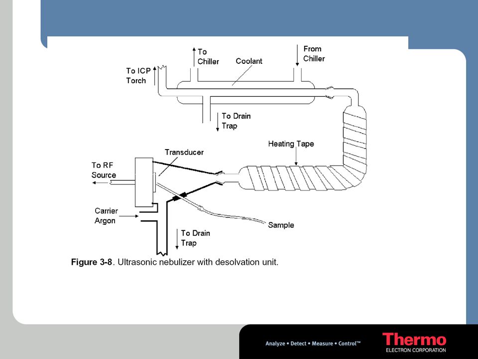
Introduzione campione liquido Nebulizzatori & Spraychambers Sistemi di desolvatazione HPLC Flow Injection Introduzione campione solido ETV Laser Ablation Introduzione campione gassoso Generatore di vapori Gas cromatografo

15
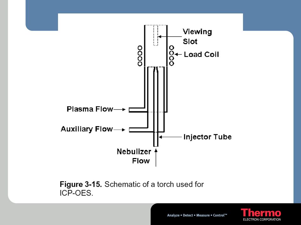
Sample Introduction – 1st stage
Inductively Coupled Plasma(ICP) Torch Spray chamber assembly Gas source Sample source Drain Load coil Coolant gas plasma gas Tesla spark Matching network RF generator
 Torch. Spray chamber assembly. Gas source. Sample source. Drain. Load coil. Coolant gas. plasma gas. Tesla spark. Matching network. RF generator.")
16
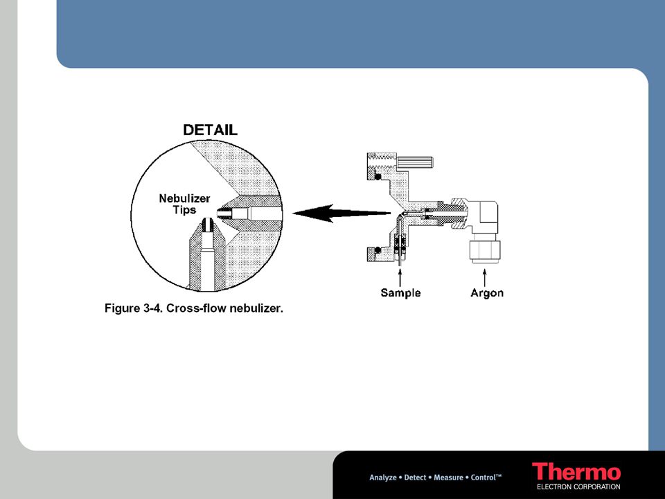
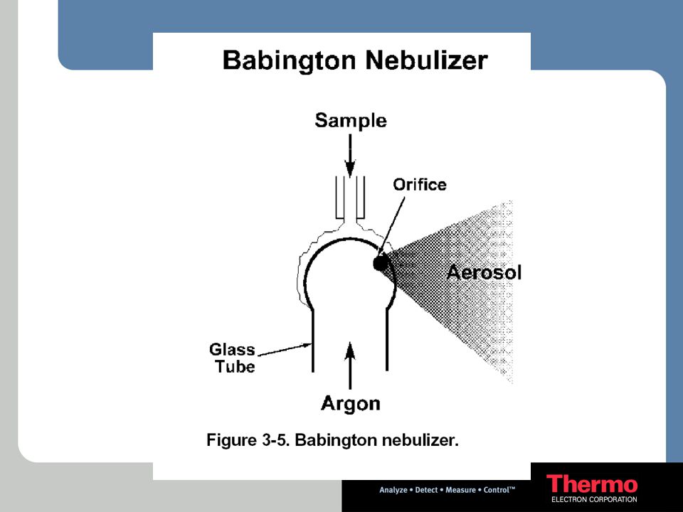
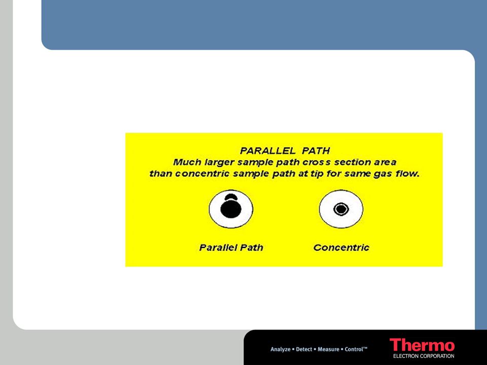
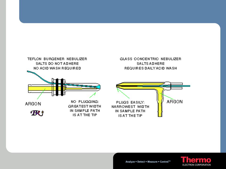
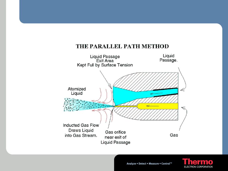
Sample Introduction – Aerosol formation
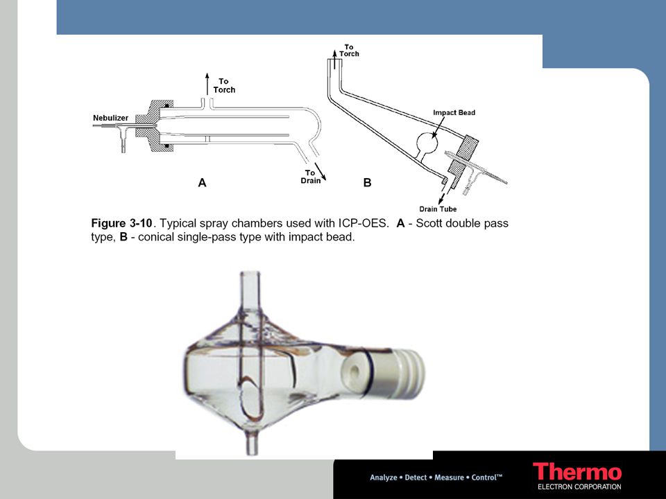
The fundamental purpose of the nebulizer is Formation of Aerosol and the fundamental purpose of the spray chamber is Aerosol Filtering

17
Droplet size No. of Droplets too large Droplet size ~10micron
Only this region should pass to the plasma H.Willard, LMerritt, J.Dean, F.Settle:Instrumental Methods of Analysis; Wadsworth Publishing Company

18
Controllo di temperatura ad effetto Peltier
Blocco a temperatura variabile Peltier (thermoelettrico) Controllo rapido e preciso della temperatura della camera di nebulizzazione Passaggio rapido da matrici acquose ad organiche, con l’impiego del Kit organici Peltier Controller Fitted to the X7 as standard the Peltier block is electronically controlled enabling the spray chamber to be cooled and operated at a precise temperature. This can lead to reduced molecular species due to lower solvent loading in the plasma and improved Method LOD’s due to improved long term stability. Temperature stabilization between aqueous and organic analysis is reduced to ~ minutes compared to >2hours with competitive systems that use water-cooled spray chambers.
 Controllo rapido e preciso della temperatura della camera di nebulizzazione. Passaggio rapido da matrici acquose ad organiche, con l’impiego del Kit organici. Peltier Controller. Fitted to the X7 as standard the Peltier block is electronically controlled enabling the spray chamber to be cooled and operated at a precise temperature. This can lead to reduced molecular species due to lower solvent loading in the plasma and improved Method LOD’s due to improved long term stability. Temperature stabilization between aqueous and organic analysis is reduced to ~ minutes compared to >2hours with competitive systems that use water-cooled spray chambers.")
19
Sistema intelligente di introduzione campione
PICO Monitor – sistema di monitoraggio intelligente di aspirazione campione e lavaggio Aggiunta di standard interni in conformità ai protocolli Compatibile con nebulizzatori a basso flusso e convenzionali Controllo totale di autocampionatore e pompa peristaltica – Tramite ACL scripts Intelligent Sample Introduction PICO Monitor – Intelligent monitored uptake and rinse Monitors the Internal Standard during sample uptake and user defined elements (e.g. matrix elements) during washout – enables the A/S to move to the next sample in the shortest possible time WITHOUT incurring sample carry over Protocol compliant addition of the internal standard(s) Can be added on-line simply by a tee-piece or PrepLab Conventional & low flow nebulizers compatible For clinical samples and semi-con. wafer-wash samples Full autosampler and peristaltic pump control ACL scripts for enhanced productivity Accessory Control Language scripts enable the A/S and peri-pump to be programmed by the user - for example the peri-pump is computer controlled and can be speeded up between samples to improve sample washout and the A/S probe can be returned to the wash station prior to the termination of data acquisition. By using solution still in the uptake tubing to complete the data acquisition sample throughput can be considerably increased. An independent evaluation by a PQXL user has shown a reduction in sample-to-sample analysis time from 7 minutes to 2.5 minutes with the X Series using real high matrix environmental samples without any degradation in precision or MDLs. See Application Note S371AN
 during washout – enables the A/S to move to the next sample in the shortest possible time WITHOUT incurring sample carry over. Protocol compliant addition of the internal standard(s) Can be added on-line simply by a tee-piece or PrepLab. Conventional & low flow nebulizers compatible. For clinical samples and semi-con. wafer-wash samples. Full autosampler and peristaltic pump control. ACL scripts for enhanced productivity. Accessory Control Language scripts enable the A/S and peri-pump to be programmed by the user - for example the peri-pump is computer controlled and can be speeded up between samples to improve sample washout and the A/S probe can be returned to the wash station prior to the termination of data acquisition. By using solution still in the uptake tubing to complete the data acquisition sample throughput can be considerably increased. An independent evaluation by a PQXL user has shown a reduction in sample-to-sample analysis time from 7 minutes to 2.5 minutes with the X Series using real high matrix environmental samples without any degradation in precision or MDLs. See Application Note S371AN.")
20
Sample Introduction – Ionisation
The filtered aerosol (still at atmospheric pressure) then passes to the Plasma where the primary process is the Formation of IONS Cool Gas Aux Gas Load Coil Neb Gas Torch
 then passes to the Plasma where the primary process is the. Formation of IONS. Cool Gas. Aux Gas. Load Coil. Neb Gas. Torch.")
29
Plasma Formation Intense analyte emission Current
Magnetic field Flow of ions and electrons Intense analyte emission Concentric quartz tubes Sample aerosol and argon Magnetic fields Argon coolant flow H.Willard, LMerritt, J.Dean, F.Settle:Instrumental Methods of Analysis; Wadsworth Publishing Company

35
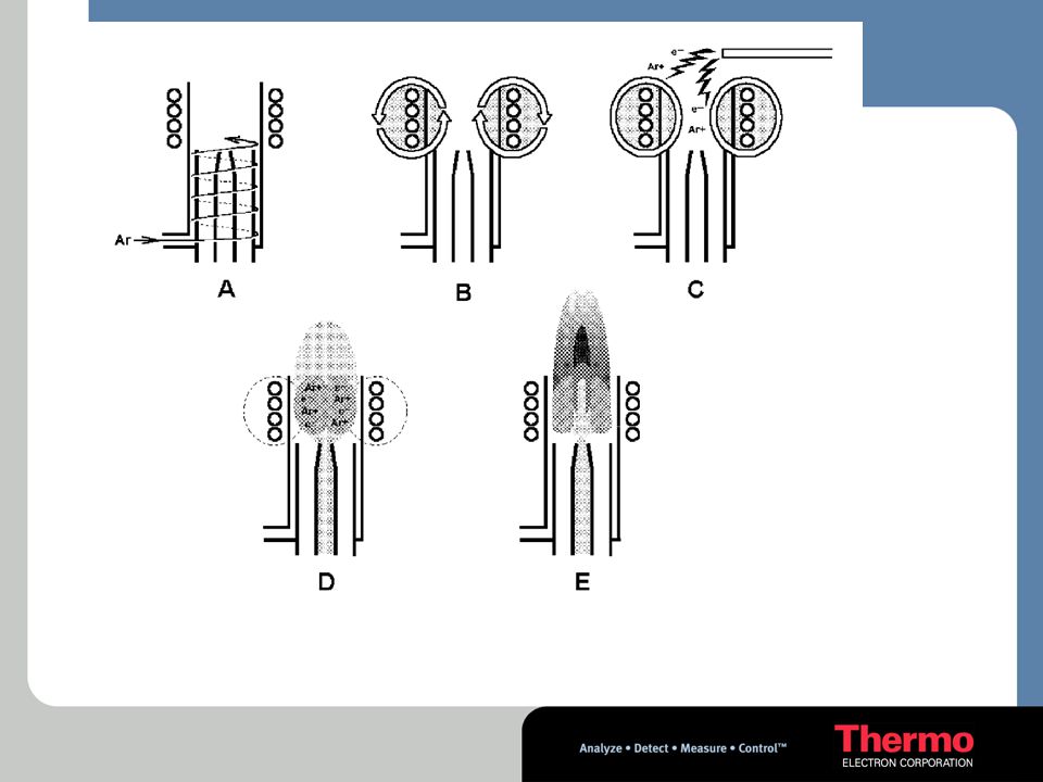
LA SORGENTE AL PLASMA Formazione degli ioni
Il campione passa attraverso il plasma e cambia da aerosol a vapore poi viene atomizzato e ionizzato

36
LA SORGENTE AL PLASMA Formazione degli ioni MO + M M+ MX (MX) n
Recombinazione MO + M(H2O) +X- Campione (viscosità, tensione superficiale,...) Distribuzione delle gocce di aerosol Desolvatazione Vaporizzazione Dissociazione Atomizzazione Ionizzazione Eccitazione Zona di preriscaldo Zona induzione Zona radiazione Zona analitica normale Flusso nebulizzato (MX) n MX M M+
 +X- Campione. (viscosità, tensione superficiale,...) Distribuzione delle. gocce di aerosol. Desolvatazione. Vaporizzazione. Dissociazione. Atomizzazione. Ionizzazione. Eccitazione. Zona di preriscaldo. Zona induzione. Zona radiazione. Zona analitica normale. Flusso nebulizzato. (MX) n. MX. M M+")
37
Ionization 80% of elements are more than 75% ionised
20 40 60 80 100 120 5 6 7 8 9 10 11 12 13 14 15 Ionisation Energy (eV) 80% of elements are more than 75% ionised Degree of Ionisation in the ICP (%) High temperatures achieved High ionization efficiency Long residence times Sample introduced at atmospheric pressure High dissociation efficiency
 80% of elements are more than 75% ionised. Degree of Ionisation in the ICP (%) High temperatures achieved. High ionization efficiency. Long residence times. Sample introduced at atmospheric pressure. High dissociation efficiency.")
38
Sample Introduction - Interface
VACUUM ATMOSPHERIC PRESSURE Sampling Cone Skimmer Cone

39
Sample Introduction – Layers and Jets
Area of Sampling Cone Area of Skimmer Cone The shape and diameter of the sample cone ensure correct penetration into the boundary layer to allow sampling of the supersonic jet Supersonic constituents only

40
Optimisation The supersonic ion beam is now
Increasing vacuum The supersonic ion beam is now optimised and accelerated along the axis.

41
NEW XSeriesII Interfacce
Xt Interfaccia standard Ideale per alte e basse concentrazioni Eccellente controllo specie poliatomiche Xs Interfaccia opzionale Alta sensibilità Basso BEC Dedicato ad applicazioni per semicon

42
Plasma Sampling Interface
Optimized interface geometry Patented sample & skimmer cone design - Large orifices 1.1mm & 0.75mm - Resist clogging - Highly resistant to matrix deposition - Low frequency of cleaning Quick release cone configuration Tailored interface options - Xt Interface as standard - Xs interface option Plasma Sampling Interface Optimized interface geometry The X-Series interface geometry has been optimized to provide high reliability and trouble free of operation. Patented sample & skimmer cone design The cones are manufactured from Ni with a special patented design that prevents condensation of matrix material onto the cones. This makes them very robust and ensures minimum cone maintenance and cleaning are required. —Quick release cone configuration The sample and skimmer cones are quickly replaced using a magnetic cone tool provided with the instrument. The sample cone has a large angled collar to channel any condensed solution away from the front interface plate – for enhanced corrosion resistance Tailored interface options are available for differing applications The Xt interface is provided as standard and a Xs interface is optionally available for applications that require higher sensitivity. The body of the Xt skimmer cone is made of a composite material with a pure Ni tip and the cone is mounted on a special alloy base plate. During normal operation this creates a temperature gradient along the body of the cone with the result that tip of the cone runs hot The temperature is ~ several hundred degrees – hot enough to prevent condensation of sample matrix without causing deformation of the Ni tip.

43
Infinity Lens & Protective Ion Extraction Optics
Hexapole ion guide provides RF focusing and the chicane deflector provides an offset between the Infinity Ion lens and the quadrupole analyser leading to very low continuum background. Protective Ion Extraction controls the ions entering the Infinity Ion lens so only ions generated in the ICP plasma with optimised energy enter the lens region – this results in improved BECs in both CCT and non-CCT mode Infinity Lens & Protective Ion Extraction Optics Ions are sampled from the ICP plasma through the sample and skimmer cone simply by differential pressure – go from atmosphere to sub atmospheric pressure. They are then extracted by the extraction lens and focused by the Pi Extraction optics the into the Infinity Ion lens The new Extraction optics ensure that only ions generated in the plasma pass through to the Infinity Ion Lens rejecting any ions that might have originated from the torch or have been sputtered off the skimmer cone minimizing the BEC for Gp I, Gp II and transition metals RF only fields are applied to the hexapole rods and these focus the ion beam and transmits the focused beam onto the entrance aperture of the quadrupole via the chicane deflector. This results in the quad and the detector being mounted off axis to the ICP source – hence we get extremely low backgrounds without needing a photon stop in the ion beam that will become contaminated with high matrix samples. Including the hexapole ion lens in the basic instrument design enables us simply to add a gas manifold and 2 MFCs to bleed in the CCT gases to convert the instrument to a collision cell instrument. Hence when we do this the normal mode sensitivity is maintained. There is no compromise to the background or sensitivity spec when the collision cell option is added and this is a USP. As can be seen the ion lens is set well back from the sample cone and so doesn’t become contaminated – any cleaning required is limited to the sample and skimmer cone and extraction lens. These are mounted in front of the slide valve and can be easily removed without the need to vent the spectrometer. The extraction lens is a simple tubular design – very robust and can be cleaned either in- situ (wiping the inside with a cotton bud) or easily removed, soaked and replaced again without venting the analyser. The Ion lens and optics are located behind the slide valve & require no cleaning by the user
 or easily removed, soaked and replaced again without venting the analyser. The Ion lens and optics are located behind the slide valve & require no cleaning by the user.")
44
Lenti Infinity – Guide ioniche ad alta efficienza
Rapida estrazione, montate in un unico modulo; esenti da manutenzione Il migliore rapporto/rumore di qualsiasi altro ICP-MS quadrupolare (minore di <1cps random background) Ottimizzazione interattiva o totalmente automatica Eccellente tolleranza alla matrice per una migliore stabilità a lungo termine e massima efficienza di analisi tra una calibrazione e l’altra Espandibile in campo con cella di collisione CCTED della terza generazione Infinity Lens – High Efficiency Ion Guide Quick release, single piece, maintenance free design This slide shows the ease of access to the Infinity Ion Lens – single piece plug-in design. Highest signal-to-noise ratio of any quadrupole based ICP-MS (typically <0.5cps random background) The Infinity Ion Lens consists of a high efficiency hexapole ion guide with chicane deflector that provides the extremely low background <1 cps and high transmission > 60 MHz/ppm mid mass providing the best S/N available of any commercially available quadrupole ICP-MS. Simple interactive or fully automated optimization Ion Lens tuning can be provided entirely automatically or via interactive tuning with real time display of user defined analyte and potential interferant masses displayed on the computer VDU. (Up to 16 isotope and 4 ratios) Excellent matrix tolerance for superior long term stability and maximum sample throughput between calibrations The excellent ion focusing means that the lens is extremely resistant to contamination providing excellent long-term stability and minimum contamination. Field upgradeable with our second generation Collision Cell Technology – CCTED It can be easily upgraded to CCT technology in the field with a “plug in module” – ½ day installation
 Ottimizzazione interattiva o totalmente automatica. Eccellente tolleranza alla matrice per una migliore stabilità a lungo termine e massima efficienza di analisi tra una calibrazione e l’altra. Espandibile in campo con cella di collisione CCTED della terza generazione. Infinity Lens – High Efficiency Ion Guide. Quick release, single piece, maintenance free design. This slide shows the ease of access to the Infinity Ion Lens – single piece plug-in design. Highest signal-to-noise ratio of any quadrupole based ICP-MS (typically <0.5cps random background) The Infinity Ion Lens consists of a high efficiency hexapole ion guide with chicane deflector that provides the extremely low background <1 cps and high transmission > 60 MHz/ppm mid mass providing the best S/N available of any commercially available quadrupole ICP-MS. Simple interactive or fully automated optimization. Ion Lens tuning can be provided entirely automatically or via interactive tuning with real time display of user defined analyte and potential interferant masses displayed on the computer VDU. (Up to 16 isotope and 4 ratios) Excellent matrix tolerance for superior long term stability and maximum sample throughput between calibrations. The excellent ion focusing means that the lens is extremely resistant to contamination providing excellent long-term stability and minimum contamination. Field upgradeable with our second generation Collision Cell Technology – CCTED. It can be easily upgraded to CCT technology in the field with a plug in module – ½ day installation.")
45
Lenti elettrostatiche
OTTIMIZZAZIONE Diffusione degli ioni oltre lo Skimmer cone Diffusione degli ioni oltre lo skimmer cone Interface Ion Optics Lenti elettrostatiche Torr 1 Torr Flusso ionico Skimmer Photon Stop + Sampler + + + + + + + + + + + + + + + + + + + + + + + + + + + + + + + + + + + + + + + + + + + + + + + + + + + + + + + + + + + + + + + + + + + + + + + + + + + + + + + + + + + + + + + + + + + + + + + + + + + + + + + + + + + + + + + + + + + + + + + + + + + + + + + + + + + + + + + + + + + + + + + + + + + + + + + + + + + + + + + + + + + + + + + + + + + + + + + + + + + + + + + + + + + + + + + + + + + + + + + + + + + + + + + + + + + + + + + + + + + + + + + + + + + + + + + + + + + + + + + + + + + + + + + + + + + + + + + + + + + + + + + High Masses + Mid Masses Low Masses Fotoni e specie neutre

46
Filtration

47
Filtration At this stage the aim is to allow at any one moment in time, a single ion to pass along the axis to the detector. The potential of one rod pair is switched with the other rod pair in such a manner that the ions move in a circular trajectory down the rod axis - The conditions at any one moment are set to only suit one ion/isotope.

48
DC vs RF -DC + RF +DC

49
+ Volts - Pole pairs Horizontal Pole Pair
Resultant Voltage arising from -DC offset & RF oscillation Vertical Pole Pair Resultant Voltage arising from +DC offset & RF oscillation

50
+ - + Mass to charge ratio
The Quadrupole filters out ions of a specific mass to charge ratio. + - +

51
RF vs Voltage DC Offset RF Area inside represents Ion transmission
For a given Ion mass, we can directly plot - RF vs. Voltage Stability in only one axis DC Offset RF Area inside represents Ion transmission

52
Quadrupole Stability Diagram and Equation 1

53
Quadrupole Stability Diagram and Equation 2
DC rod voltage Quad RF frequency Mass of ion Electron charge Inscribed radius

54
Quadrupole Stability Diagram and Equation 3
Consider only single charged ions Quad size and frequency are fixed

55
Quadrupole Stability Diagram and Equation 4
Consider only single charged ions Quad size and frequency are fixed

56
Quadrupole Stability Diagram and Equation 5

57
Quadrupole Stability Diagram
DC Offset RF M Therefore at any one point if we consider the DC offset and RF to be constant we get the following :

58
Quadrupole Stability Diagram
DC Offset M M-1

59
Quadrupole Stability Diagram
DC Offset M+1 M M-1 RF

60
Mass Scan Line DC Offset RF Mass Scan Line

61
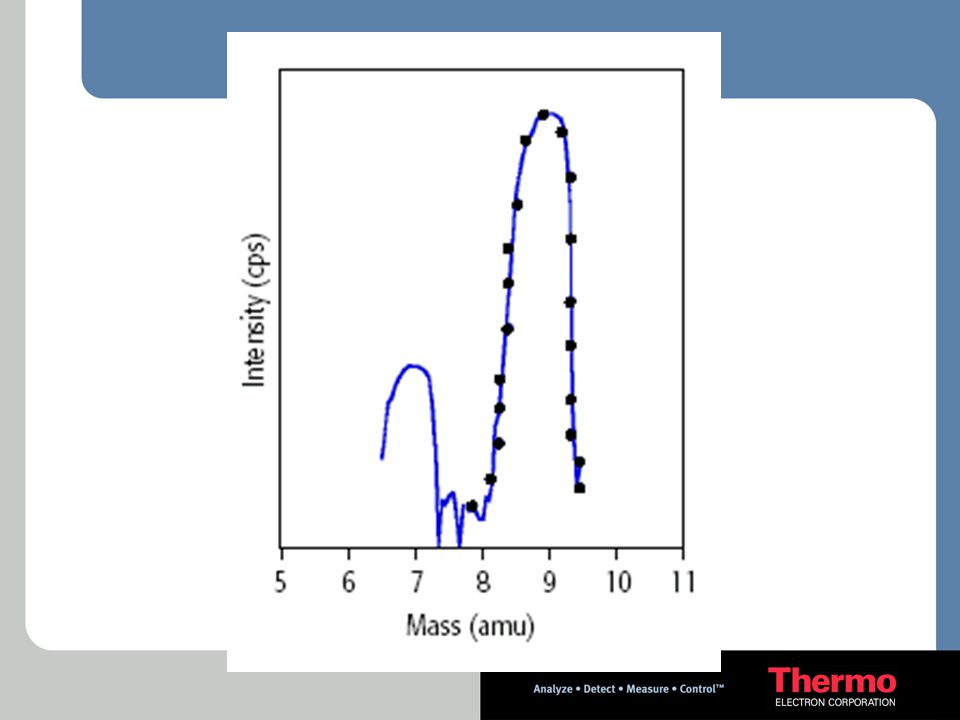
Quadrupole Abundance Sensitivity Tailing edges - 5% m-1 m m+1
Height (m-1) = 10-6 Height (m)
 = Height (m)")
62
ANALIZZATORE DI MASSA + Separazione degli ioni t+D ’t t+Dt t
m1/z m2 /z m3 /z Quadrupole Risoluzione: definizioni Capacità di separare differenti masse Si definisce come l’ampiezza del picco a 5% o 10% dell’altezza del picco Risoluzione può variare tra 0,2 e 3 amu La sensibilità è sacrificata per la risoluzione Il quadrupolo lavora ad una risoluzione di 0,2-1,0 amu

63
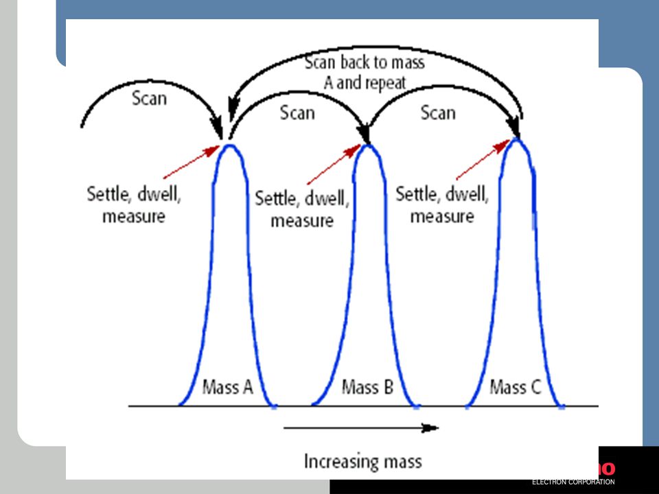
ICP-MS Quadrupole MS Abundance Sensitivity
Measure of signal due to analyte at one mass higher and one mass lower than analyte Abundance sensitivity typically > 1e6 at M-1 and 1e7 at M+1

68
Detection

69
Detector

70
Detector Response for Indium Analog detector Log Counts per second
0.1ppt 10ppt 1ppb 100ppb 10ppm 1000ppm Concentration 0.0001 0.01 1 100 10,000 Response cps Response for Indium Log Counts per second Pulse counting detector 0.1 1 10 0.1 1 10 0.1 1 10 100 1000 ppt ppb ppm Concentration

71
Dead time correction Counts Conc. Dead time correction
Corrected counts Actual counts PC not usable in this range Counts Conc.

72
Sistema di rivelazione ad alte prestazioni
Range dinamico lineare > 8 ordini di grandezza Sistema intelligente di protezione dalle sovraesposizioni Sistema di calibrazione incrociato completamente automatico per garantire una superiore linearità Avanzata elettronica di conteggio analogica a rapida commutazione Ba at 7ppm High Performance Detector System > 8 orders of magnitude dynamic range Intelligent over-range protection Fully automated detector cross calibration providing superior linearity Advanced fast switching analog counting electronics The new X Series ICP-MS has extremely fast analog to digital conversion electronics with unprecedented signal to noise for the analog stage of the detector. This leads to a cross calibration that is not only much more accurate than previously achievable with traditional electronics but also much more stable with time. A new propriety design for converting the pulse counting signal into a data stream has lead to detector plateaus that are much flatter than previously achieved, even on an aged detector. This leads to much- improved long term signal stability and cross calibration stability between detector modes. The graphs illustrate the excellent detector cross calibration across the Ba isotopes varying from 0.1 to >70% abundance plus fast recovery following a detector trip into analogue mode. Pulse Counting Analog

73
X Series ICP-MS – System Overview

74
Sample Introduction System

75
Sample Introduction System

76
Interface

77
Ion Optics The INFINITY LENS comprises of a high efficiency
ion guide and a chicane deflector, coupled to an off-axis detector.

78
Quadrupole

79
Detector

80
Data Acquisition

Presentazioni simili


![2po 2p- [He] (2s)2 (2p)2 Il carbonio (Z=6)](/2/575569/big_thumb.jpg "2po 2p- [He] (2s)2 (2p)2 Il carbonio (Z=6)>")


 0.8 mm pitch M = 2, FoV = 25×25 mm 2 50×50 mm 2 LaBr 3 (Ce) 4 mm thick, 3 mm thick window M = 2, FoV = 25×25 mm 2 50×50 mm 2 CsI(Na)>")


